
A number of people have inquired about ignition keyhole lights. I was able to build a simple circuit that would come on when the doors are opened. However once the ignition key is inserted and turned, the light will automatically turn off.
All the parts were bought at Radio Shack (with their Radio Shack part number), except for the 12V diode, which I already had.
Don't forget you will need solder (Radio Shack part number 64-006 B), a soldering iron (a cheap one will do, or borrow one), and splice connectors 3 red and 1 blue (red and blue are size types). Optional item would be a 4" length of 1 1/2" diameter shrink tube and a 2" length of 1" Velcro tape.
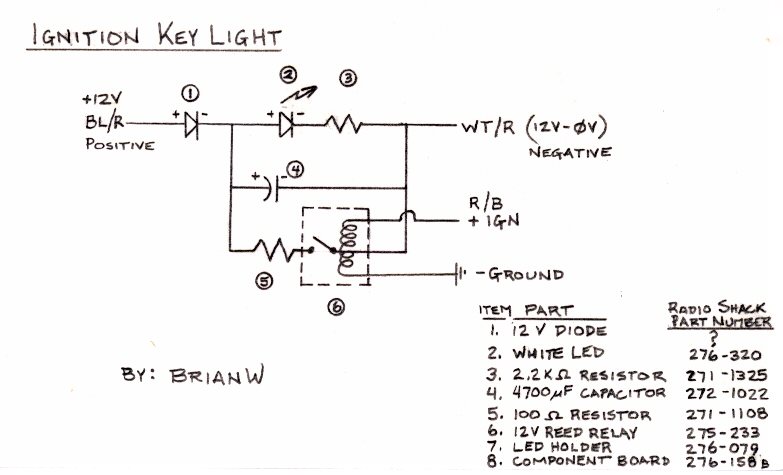
It is very important that the LED diode and capacitor be installed in the correct direction (see the + and - sign on these components in the diagram). If they are not installed with the right polarity (current flow direction) they could quickly burn out if the current goes the wrong way. The resistors and the relay have no polarity preference.
Make the wire leads that go to the 12V supplies (Blue with Red stripe BL/R and White with Red stripe WT/R) 26" long.
The ignition wire, IGN (Red with Black stripe) 8" long.
The ground wire 16" long.
The leads to the LED light 6 1/2" long.
I ended up cutting the excess circuit board off leaving a compact unit. Here's a picture of the completed circuit board.
At this point, I used a 12V source to test the light charging circuit (BL/R and WT/R) leads. I then tested the relay with 12V supply to ensure it discharged and turned the LED off.
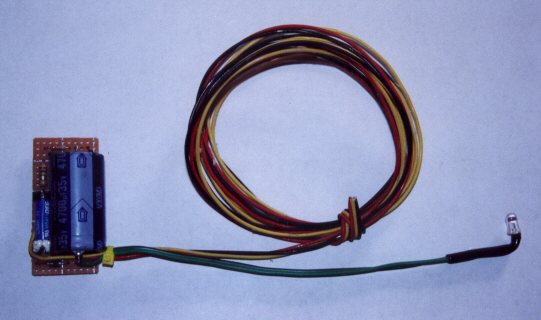
In this picture you can see the circuit with the 1 1/2" diameter shrink tube shrunk down over the board. I secured it to this location with the optional Velcro tape.

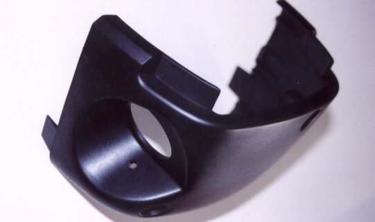
Remove the lower plastic piece of the plastic steering column. You will need to remove the 3 Phillips screws (+ head screwdriver). Note the hole where each screw comes out, one screw is different, so keep that location straight. The upper and lower plastic clamshell pieces will now be able to unsnap apart so that you can remove the lower clamshell. At this time you might as well remove the two Phillips screws from the flat 10" x 16" rectangular plastic steering column cover piece. The screws are by the bottom dash edge of the cover. Then by sliding the cover down to remove it you will have all the wiring access needed.
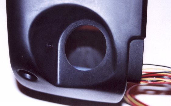
Drill a 1/4" diameter hole in the lower clamshell in the keyhole notch location. See the picture below. (LED holder is also installed in this view).
Insert one of the LED holders (item 7) from the outside, with the tabs on the inside of the column cover (as shown in the above photo). Gently press the LED from the inside into the holder (see photo below) and secure the circuit board if desired with the Velcro.
At this point I again tested the circuit function to ensure that the unit still functioned properly
The 12v supplies hook into the wires that supply the dome light. They are located in the driver's side foot well about 6 inches aft (towards the rear of the car) from the footrest and about 3" above the edge of the carpeting. Look for a white connector plug with only two wires feeding it. The two wires are both loosely in one 1/4" diameter black piece of tubing. The two wires are color-coded; Blue with Red stripe BL/R and White with Red stripe WT/R. Once you have located the wires you will need to slice the black tube wrapping back a bit so that you will be able to get your 2 "red" splice connections in.
The ignition wire is located going into a large white connector between the Mazda fuse panel and the steering column (the connector looks like it’s 2" x 2" with about 30 wires). You should be able to find the wire it is color coded Red with a Black stripe (R/B). You will need to use your large "blue" splice connector here.
The ground wire can be hooked up to a ground point that attaches to the bare formed sheet metal by the steering column. You can use a screw or clip to hold secure the ground wire to the bare metal.
At this point test it once again, if all is well, you should be able to neatly tuck the wires up and reinstall and screw in plastic parts.
You should have an ear-to-ear grin the next time you get into the car at night, and you can easily see the illuminated keyhole!!!
| Back to the Garage |
22 November, 2001 |
[Home] -
[FAQ] -
[Search] -
[Sponsors] -
[Forums]
[Garage] -
[Clubs] -
[Contact Us] -
[Disclosures] -
[More...]
Copyright
©1994-2024, Eunos Communications LLC
All rights reserved.