
By Ross Kuhre (Stock 93 MX-5, C package,
130k mi)
If you have an idle
problem with the unmodified NA 1.6L engine, this article is intended to help
you understand how the ISC (Idle Speed Control) system should work
and how it may fail (my experience). If
you isolate your problem to the ISCV (Idle Speed Control Valve) this article
may also help you find replacements or in special cases, make repairs.
If
you are just curious about how the ISCV operates and is constructed you can
jump to the VALVE OPERATION section at the end of the article.
Abbreviations & Acronyms: It was my intention to only define them the
first time they are used.
System Description
The ISC system has two components exclusively
dedicated to idle air / rpm control. Those
are the ISCV and the AV (Air Valve). Other components play roles in the idle rpm,
including the IAS (Idle Adjustment Screw), which is part of the throttle body.
This screw may or may not be under a “Blanking Cap”.
The IAS is a simple air bypass needle that controls air in a passage
around the TB (Throttle Body) butterfly valve.
This path is separate from the ISCV & AV paths.
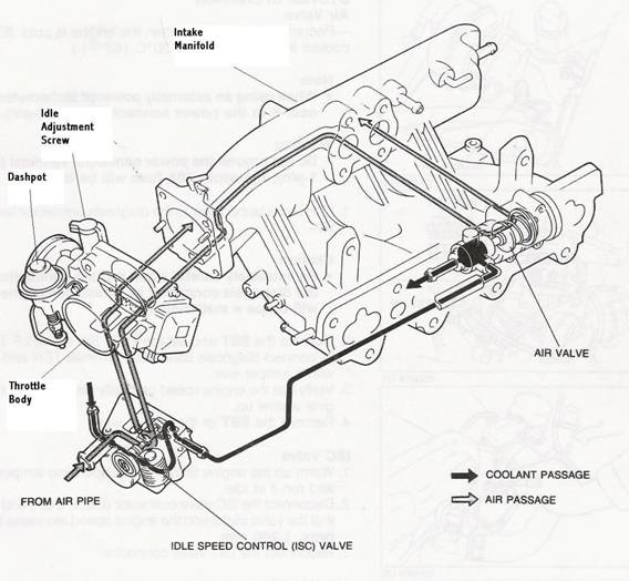
The
Miata Workshop Manual has the following description
with this diagram. “To improve idle
smoothness, the ISC system controls the intake air amount by regulating (the)
amount of the by-pass air that passes through the throttle valve. This system consists of the air valve that functions
only when the engine is cold, the ISC valve that works throughout the entire
engine speed range, and the control system.”
The
“control system” mentioned in this description is primarily the ECU (Engine
Control Unit). Normally, with input
signals from Ignition rpm, Temperature, Throttle Position, and Air Flow sensors,
the ECU operates in a control loop and adjusts several engine components including
the ISCV. A signal to the ISCV from
the ECU controls the amount of bypass air into the intake manifold and thereby
the idle rpm. It is possible
for bad rpm and temperature sensor inputs to create bad ECU commands to the
ISCV. However, when the DC (Diagnostic
Connector) TEN & GND contacts are shorted together for Self Diagnosis
and troubleshooting the ECU control loop is opened. With the control loop open, the ECU ignores
inputs from Ignition rpm, Temperature and Throttle Position sensors and sends
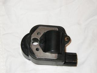
a fixed signal to the ISCV. This should
produce a stable idle value for troubleshooting & fault isolation. (More on that later) Here’s a Picture of the complete ISCV.
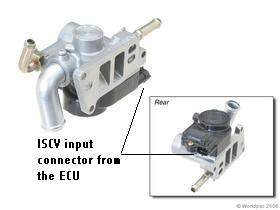
The other dedicated ISC component is the AV (picture later).
The AV is a “Dumb” device. It is simply a wax pellet driven thermostatic
valve. When working correctly it gradually
closes its idle air bypass ports to the IM (Intake Manifold) as the
coolant flowing through it comes up to the full engine-operating temperature.
WARNING: THE READER
IS ADVISED THERE ARE HAZARDS PRESENT WHILE DOING THESE PROCEDURES. THE READER TAKES FULL RESPONSIBILITY FOR DAMAGE
OR INJURY TO ANY PERSON OR PROPERTY INVOLVED.
Trouble shooting:
I
suggest you read completely through each section before taking any action.
Here
is a brief description of my failure symptoms.
I suddenly began having erratic idle rpm behavior. The symptoms varied from dying at idle, idling
around 2k rpm and anything in between including normal rpm. The symptoms did not often remain the same for
long periods. I found that if I stopped
the car, turned off the key and restarted the engine, the symptoms would often
change. The engine ran normally at
highway speeds. In the end, I discovered
I had 2 problems.
1. I had a dirty (Gummy)
ISCV. My ISCV had not been cleaned
for at least 70K miles.
2. I also had an intermittent
& varying high resistance failure at the ISCV Solenoid (approx 60 to 180
ohms). After I cleaned the ISCV the
dying at idle symptom disappeared. At
first, solving the grunge problem led me away from the ISCV, thinking I had
eliminated any problems there. Furthermore,
my ISCV passed the “Click” test, which you may read about elsewhere.
Therefore, I consider the “Click” test inconclusive.
After the ISCV was cleaned my idle rpm values were high, unstable or
normal. The dying symptom disappeared.
Here
is my suggested troubleshooting approach:
To Start, I will assume you had a normally running and idling engine.
Suddenly, for no apparent external reason, the warm engine will
not idle consistently at the correct rpm (800-900 rpm).
Fight the normal urge to immediately adjust the IAS.
This action might temporarily seem to correct the problem but will
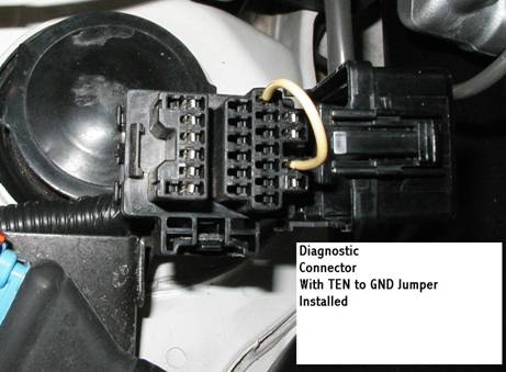
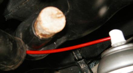
probably only mask the real problem. Find
the DC next to the engine, above the upper shock absorber mount on the driver’s
side of the car. See the picture below.
Warm
up the engine to operating temperature. This
value has always been near mid scale on my Temperature Gauge. Turn off the heater & A/C blower
controls inside the car. If you’ve
had A/C trouble you should probably confirm the A/C clutch is also not
engaged. On a pad, note your current
tachometer idle rpm value. If it is
unstable note the range of values. With
the engine still running at idle, connect the TEN & GND contacts in the
DC (14 awg solid copper wire worked for me). Note the 2nd tachometer rpm value. Do not make an adjustment of the IAS at this
time. If your engine will run smoothly
with the throttle held slightly open but will die or not idle at 800
rpm or higher, move to the Cleaning part of this article.
Shorting the TEN to GND contacts in the DC enables
the Self Diagnostic feature of the ECU. If
you are lucky you will have a blinking error code being displayed by your
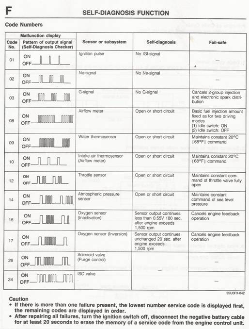
instrument panel Check Engine light. Below
is the table from the Miata Workshop Manual to decipher
what these blinking error codes mean. For example, if you have an open coil in your
ISCV you should see 3 long blinks followed briefly by 4 short blinks. This is the 34 error code, indicating a problem
with the ISCV. This code will repeat
over and over. I had no error codes
displayed. Note the remark at the bottom
of the table that says you will need to remove the Negative battery terminal
to get this code to disappear after you repair a failure. I found this was not always the case. For example, when I removed the ISCV connector
creating a “simulated” Open ISCV solenoid or broken wire from the ECU to the
ISCV, I only needed to reinstall the connector and the 34 error code disappeared.
However, I did have to remove the Negative battery cable to clear a
09 code that I set by removing the connector on the Water Thermosensor. Technically, when I “opened” the Water Thermosensor, I got what appeared to be a 19 error code (One
long pulse followed by 9 short pulses). I have no explanation for this apparent
table discrepancy but the reader might be on the lookout for other code mysteries
like this. Obviously, since I had
created this “error” condition on purpose and there is not a 19 code in the
table, I disregarded the discrepancy. There may be a logical explanation and some
reader smarter than I will probably inform us about that, later on this site.
Sorry, I don’t have a comprehensive list of which codes are cleared
without removing the Negative battery cable.
Try the easy way first then remove the Negative battery cable if necessary. By the way, it does need to be the Negative
cable. NOTE: Be sure to have
the Positive battery terminal well covered as you may be reaching across the
battery with a ratchet & socket extension to get to the Negative terminal.
This process creates the real risk of shorting the battery.
That is a dangerous event. I
covered the Positive terminal and then still chose to use a short 10mm open-end
wrench that was not long enough to reach from terminal to terminal.
If
you do not discover any error codes continue from here. Check for any cracked or loose vacuum tubing
that is connected to the IM. Check
both ends of the tubing or, if the IM end is good, pinch off
the tube temporarily with pliers to see if a change in idle rpm occurs. A decrease in rpm means air was passing through
that line. In my case, this process
revealed I had a small leak in my PCV valve. Unfortunately, after replacing the existing
PCV valve twice, I found the original one had the smallest leak of the three.
So, for the time being I chose to leave it in and temporarily accept
a 50-rpm increase in idle speed. This leak was obviously not my core problem.
Next,
turn off the engine and eliminate the AV as the culprit. Once the engine is warm the AV should close
and allow no bypass air through it, into the IM. There is a workshop manual procedure to remove
the AV, Freeze it, mark its shaft, then Heat it & confirm the valve shaft
moves and is closed when Hot. If
you choose to do this you will need to deal with the coolant that is in the
AV coolant lines. I simply pinched
off these tubes with small clamps or a small smooth flat jaw vise grip pliers.
If you want to perform this test, install these clamps just
far enough away from the AV to give you space to move the hose clamps back
off the AV metal coolant tubes. Put a rag under the AV, as you will have a small
amount of coolant trapped in the AV when you remove it. Because I had intermittent symptoms, I chose
to reinstall the AV with a DEG (Dead End Gasket) to totally eliminate
the chance that the AV was occasionally sticking and allowing idle air into
the intake system (see the picture). NOTE: If you let the engine cool with this gasket
in place, you will need to manually hold the Throttle open until the engine
warms to operating temperature if you re-start the engine.
You
can fabricate this temporary DEG from common gasket material as I did.
Install it between the AV and the intake manifold.
When you reinstall the AV be sure the factory O-ring gasket stays on
the AV side of the DEG. It is not necessary to disconnect the coolant lines
to make and install this gasket, as only air passages are open when the AV
is separated from the IM. The four 8 mm mounting bolts have a recommended
torque of 43-69 in. lb. While you have
the AV removed for either procedure, clean the air passages with throttle
body cleaner. NOTE: Remove the
rubber O-ring gasket before cleaning the AV. Some cleaners may distort the rubber and cause
it not to fit correctly. If the gasket
is in poor condition and possibly leaking, replace it. If you have not localized the problem continue.
Leave
the TEN & GND jumper IN. Do not
touch, tap or disturb any components under the hood. Restart the engine. Note a 3rd tachometer value. Stop the engine, pause about 10 seconds then
start the engine again and note the 4th tachometer value. While the engine is still at idle, remove the
TEN, GND jumper. Note the rpm value
again. Now you should have 5 tachometer
readings. If readings 2,3, & 4 are not equal and/or not between the 750 &
1K marks on the tachometer, it is very likely either the ISCV or AV (if you
did not isolate it) is the culprit. The
first remedy I would try is cleaning.
CLEANING:
A first non-invasive cleaning can be attempted
by spraying throttle body cleaner (I used Berry B12 carb.
& TB cleaner) into the air supply tube to the ISCV with
the engine running. It is possible
to remove the front end of this tube near the throttle body and seal the black
molded plastic intake air chamber port with a cork. (see picture)
When
spraying the cleaner you may need to keep the engine from dying by hand controlling
the throttle control on the side of the Throttle Body.
After
this external cleaning, remove the cork and reinstall the air tube to the
ISCV. Now redo the idle check outlined
above. If the second set of values
are still incorrect but not the same as set #1 (at the same Temp.), I suggest
you remove the throttle body, remove the ISCV and clean them directly with
throttle body cleaner. NOTE:
When using the cleaner do not spray the rubber O-ring gasket.
Some cleaners can distort this rubber so it will not be reusable. You
will need to remove only the TB end of the black air chamber tubing that runs
from the air cleaner to the TB. The
rest of the air inlet tubing needs to be loosened but not totally removed. TB removal requires the removal of only 2 bolts
and 2 nuts (12mm). A 3rd
bolt (10mm) holds a piece of the air tubing below the TPS (Throttle Position
Sensor) connector. Disconnect the throttle
control cable from its attach point on the side of
the TB. This is done by manually rotating
the throttle wheel to full open (CW). Then,
with the cable slacked, remove the cable end through the slot on the side
of the throttle wheel. You also need
to remove the inlet air tube that is connected to the ISCV. When you get the TB free remove the ISCV &
TPS connectors. If the vacuum line
from the Cruise control is installed you will probably want the TB end of
it removed also. You will need to disconnect
the coolant lines attached to the ISCV. You can simply pinch off these lines close to
the ISCV (as detailed for the AV) or drain coolant from the system until it
is below the ISCV level. In either
case there will be some coolant to catch with a rag from the hoses and valve
when you make the final separation. Separate
the TB and ISCV by removing the 3 screws holding them together. Watch for the O-ring gasket and set it aside. While you have the TB removed clean it carefully
without removing the factory seal material, which is around the rim of the
butterfly valve and seat. Confirm the
Butterfly is not sticking and is fully closed at rest. This might be a good time to confirm the dashpot
(see first Diagram) is not preventing the throttle from closing completely. It should cause the throttle to slow when it
first makes contact but not keep it open after that initial delay. If the throttle valve remains open and the dashpot
is not to blame, look for and determine whether the throttle stop screw is
at fault. If so, adjust it to touch
the throttle stop plate at the zero open position. I used a strip of printer paper and set the
stop screw so the drag just barely let me pull the strip out without tearing
it. Clean the rotating valve area inside
the ISCV and confirm the shutter valve rotates freely but returns to a position,
open about 20%. (see pictures in VALVE OPERATION section) While you have the
ISCV removed, use an ohmmeter to measure the resistance between the pins on
the connector. The Miata
Shop manual calls for a value of 12 +/- 1 ohm.
Remember to adjust for the resistance of your meter leads. If you have a resistance of 0 or below 11 ohms
you probably have a short between windings in the ISCV solenoid. Double & triple check yourself here to confirm
you are not shorting your leads as you probe the connector pins or have a
defective meter. If you do indeed have
a shorted or low resistance reading, I think you should look for a replacement
ISCV. (See REPLACEMENT section) If
you have a reading higher than 13 ohms you probably have an open wire or high
resistance connection in the solenoid. If
you can, use test leads with alligator clips to connect your meter to the
connector pins. (See picture in REPAIR
section) While you have this static
connection, tap the black body of the ISCV around the coil and connector with
the plastic handle of a screwdriver. If
you don’t have the alligator test leads, try to clamp the ISCV in a vise (carefully!)
so you can have both hands free to accurately touch the probes to the pins
when you take resistance readings. If
your resistance reading changes after a tap, it is possible you have a repairable
problem. (See Repair section) This
is where I found my 2nd problem. I had an intermittent & varying high resistance
reading of about 60 to 180 ohms. Your
readings will likely not be the same as mine or may even be “Open or infinite”.
ADJUSTING
THE IAS. If
you have cleaned &
checked the TB, the ISCV, and the AV per the preceding steps and have found
and corrected a problem, I would now reassemble the parts & adjust the
IAS to 850 +/- 50 rpm with the TEN & GND contacts shorted in the DC. Ideally the rpm will be the same (850 +/_ 50
rpm) with or without the TEN & GND jumper installed.
REPLACEMENT:
If you localize your problem to the ISCV as I did, you have
several options.
1. You can search the net
or contact dealers for new parts. I
did a search on the net and found the cheapest new ISCV I could find
cost $514.00. If this seems reasonable
to you, order and install that ISCV. OH
yeah, and send me your old one!!
2. You can also do a search
of salvage yards on the net. I found
several sources for a used ISCV. All
the used sources I found sold the ISCV as part of the Throttle Body. This might be a way to pickup a spare TB if
you are into stocking “spare” parts. The prices I found for this used part
ranged from $75 to $250(+ shipping ). Some sites showed a 30 day guarantee on their
parts. I would try to get this guarantee
specified for the ISCV. Some places
have a disclaimer that excludes Electrical parts and this would likely be
in that category.
3. You can also go to local
Salvage yards to search for a used unit. I
could not find any used Miatas in my area salvage
yards. However, I found a “You Pull
It” yard which had an early 90s era (sorry exact yrs unk)
Mazda Protégé with the engine dumped in the rear seat. Earlier, on a Miata.net forum I had read a post
that said the ISCV was interchangeable between the NA Miata
and some Protégés. As noted in that
post the Protégé ISCV has different cooling tubes.
I worked around this by buying new 5/16th ID tubing and
running longer coolant line(s) to/from the ISCV. The used Protégé ISCV was available for $20
+ tax. I think I got lucky!! Before I pulled the ISCV I took a resistance
reading and found a solid 12 ohm +/- 1 ohm value at the connector. I suggest you also ask any mail order source
of used parts to take this resistance measurement before you have them send
the part. I pulled the used unit and
also took the O-ring seal and the in/out coolant tubing. One of these coolant lines was useable in my
Miata for the line between the ISCV & AV. The used unit I bought needed to be cleaned
of Gummy carbon before it functioned properly.
I installed the used unit. (ISCV
to TB screws, 25-35 IN.-lb) & (TB to IM bolts, 14-19 ft-lb) The gasket between the TB & IM was broken and needed to
be replaced. I found one at my local
Auto Zone, P/N 60874 for $2.99. (I
have no local Mazda dealer)
ADJUSTING
THE IAS. If
you have cleaned &
checked the TB, the ISCV, and the AV per the preceding steps and/or have found
and corrected a problem, I would now reassemble the parts in reverse order.
Start the engine and warm it up. Adjust the IAS to 850 +/- 50 rpm with the TEN
& GND contacts shorted in the DC. Ideally
the rpm will be the same (850 +/_ 50 rpm) with or without the TEN & GND
jumper installed. You should be ready
to go zooming, unless you need to clear an error code or take out the trash!!
REPAIRS
??: Now
the fun begins!
Having an “abnormal” curiosity and having repaired other
potted modules in the past, I decided to attempt the repair of my “bad” ISCV.
Later, I also decided to disassemble the unit to learn how it operated
and was constructed. I already had a fully functioning replacement
installed so there was no real pressure. Following
is a description and pictures of that repair process. NOTE:
This process can very easily result in an ISCV with an open resistance
solenoid. This should not leave you
any worse off than your failed condition. However, if you are not prepared
to replace this unit with one from another source do not proceed. Furthermore, if you have any hope of using the
ISCV again, do not disassemble it as I did.
There are virtually no repairable parts inside the ISCV body. Instead, see the VALVE OPERATION section where
I have already disassembled the valve for our enlightenment.
Remember,
my failure symptoms were a varying high resistance condition and usually changed
as a result of my tapping the ISCV solenoid module.
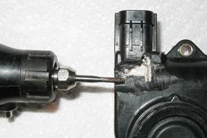
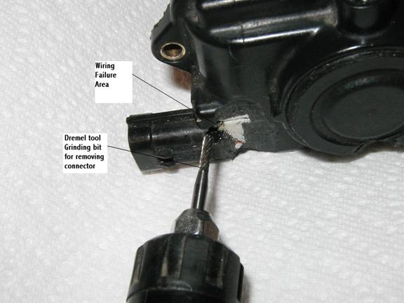
From past experience I suspected the problem
might be a bad connection or broken wire at the rear of the male connector
pins. Therefore, I decided to delicately
grind into the rear of the connector, planning (ok, hoping) to locate the
coil wire connections without destroying them.
I used a Dremel tool with a 3/32nd
spiral grinding bit.
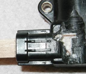
The first thing I did was decide how far back from the edge
of the connector to start grinding. I
measured the inside depth (Popsicle stick pic) from
the outside end of the connector edge to the bottom of the pins. This was about ½”. I added ¼” for connector pin potting material
in the body and decided the rear of the pins were “probably” about ¾” from
the outside edge of the connector. (Sorry, these pictures were taken after
the process, as I did not know at the time I would write this article)
I was unsure how the wires
exited the back of the connector pins so I started grinding about 1” back
from the outside edge, taking small amounts of material at a time and watching
closely for different material. I
used a 10X magnifying visor for better visibility.
This process takes patience and a little luck. When I found a cavity or change in material
type, I took a small metal pick and removed bits of material to investigate
before grinding further. After I exposed
both wires, I was able to determine using the ohmmeter which one was at fault.
I found the inboard “connector pin to wire” connection had failed.
By grinding and picking my way down to the brass pin, I was able to
clear space on the back of the pin and solder the coil wire back to the pin. This connection may have originally only been
crimped. For that reason, I have a
hunch many Miata ISCVs
fail this same way.
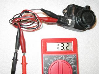
This was the resistance reading
after the repair was completed. Keep
in mind I have about 1 ohm resistance in my test leads. Therefore, the actual reading is about 12.2
ohms.
All
that was necessary to put this ISCV back in service was to seal the “disturbed”
area with High Temp. Black Silicone sealant. The resulting ISCV is probably “Better Than New” as a used car salesman friend used to say. NOTE: There is no need to remove this
Solenoid module from the body of the ISCV to attempt this repair. It is only removed in these pictures because
I had removed it as part of the following article section.
VALVE OPERATION / CONSTRUCTION:
This
valve is a rotary solenoid with a flat coil return spring. The armature of the solenoid is pressed onto
a rotating shaft carried by two precision bearings. Between these two bearings is what I will call
a cylinder segment plate or shutter. This
shutter sits behind a matching curved window in the body of the ISCV. This shutter adjusts idle air/rpm by rotating
clockwise (CW) (viewed from spring end of shaft) off its stop and metering
bypass air into the IM. The (ECU) controls
the current through the solenoid coil and thereby the CW rotational force
applied to the valve shaft. The return
spring opposes this CW rotating force with a CCW force. Where the two forces equalize is where the shutter
sets in the window and determines the amount of idle air bypassing the TB
butterfly valve. When no power is applied
to the solenoid (connector removed) the shaft is rotated CCW by the return
spring and the shutter rests against a stop screw. In this “no power” or at rest position the valve
allows “approx” 20% of the air it would pass if fully open. This explains why removing the connector at
idle normally causes an increase in idle rpm.
Here
are a series of photos of the separate parts.
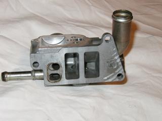
This is the ISCV body with
all parts removed. The top of the body
in this picture is where the solenoid module is nested and attached with 3
screws.
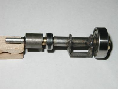
This is the ISCV shaft. From the left, the primary parts pressed or
welded on the shaft are:
The highly magnetic solenoid
armature cylinder, next, a short brass spacer, next, the small bearing, next,
the shutter valve plate (spaced off the shaft), next, the larger bearing (labeled
Japan NTN 635Z) and then a small brass ring pressed on the right end.
This is a view of the “bottom”
or hidden side of the solenoid module, which mates to the metal valve body.
You can see the coil location and the stator arms that bring the magnetic
field from the coil to the armature core on the shaft.
Barely visible in this picture is a rubber gasket that goes around
the outer perimeter on this surface of the module and seals it against the
metal valve body. NOTE: Three screws attach this module
to the metal body. Only one of these
screws is visible when the unit is fully assembled. The other two are hidden inside under the Return
Spring. You can see where they pass
through the metal stator bars in the picture above.
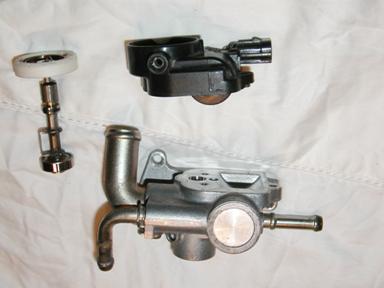
These
are the major parts that make up the ISCV.
They are oriented as they would be if they were assembled. NOTE: The white ring on the end of the
valve shaft is the Return Spring. See
the next picture for a better look at this spring when it is removed from
the shaft. Also notice this view looks
into the “Return Spring Set Screw Hole” on the outer circumference of the
black solenoid module. I strongly suggest
that this screw not be turned. There
is surely a factory pre-set tension applied to the return spring. That correct pre-set tension
will likely be lost if this screw is backed out even a few turns. That pre-set CCW tension would be critical to
resist the CW rotation of the valve shaft when current is applied to the solenoid
by the ECU.
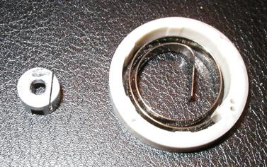
This
is the Return Spring and the white ring that is molded onto it’s
outside end. The silver component is
a return spring to shaft adapter that slides onto the valve shaft. Notice the offset slot is where the inside spring
end sets when installed on the shaft. Also
be advised there is an internally toothed spring washer that goes on the end
of the shaft to hold the items in place.
Here
are a few other Misc. views of the ISCV parts.
This view is looking into
the end of the shaft hole where the larger shaft bearing seats on the side
of the body opposite where the solenoid module sets. Also notice the Shutter
valve Stop screw appearing in the left side of the hole just beyond the bearing
seat. The shutter plate rests against
this screw when no power is applied to the solenoid and the return spring
pre-tension sends the valve to this location.
Also notice visible on the other end of the shaft hole is the smaller
hole where the shaft and armature exit the body. Remember that the smaller bearing is on the
shaft on that side of the armature and essentially seals off that upper hole.
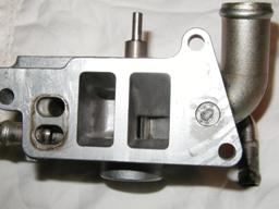
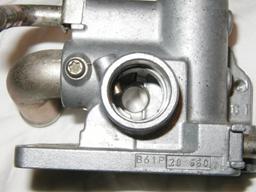
This view is looking into the two rectangular
air outlet ports on the side of the ISCV that mate to the TB. These ports are isolated from one another and
the coolant passages (far left) by the special O-ring gasket sandwiched between
the ISCV and TB. In the back of the right port (the Warm idle port)
you can see the shutter valve installed (see armature at top where solenoid
module would be attached). The
valve in this picture is resting against the stop screw out of sight on it’s
right. Notice the valve is actually
open in this position approx 20%. This
is the no power, failed open coil, or connector removed, position of the valve. Note that from here the valve shutter can only
move/rotate to the left (CW, from above) and must pass through the actual
valve closed, no air position to get to the normal operating positions
where it operates when driven by the ECU.
If the engine dies at warm idle and the ISCV is dirty, the shutter
is probably stuck in the closed area.
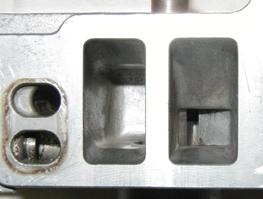
This picture shows the valve rotated CW off the stop screw
and past the fully “closed” position. This
position is much as it might be during normal operation.
The left air passage is the Cold idle
port and leads through an isolated passage in the TB and IM to the AV and
back into the IM, causing the idle to be higher during warm-up. This port is not controlled by the shutter valve
but should only have air flowing through it until the AV warms to operating
temperature and fully closes.
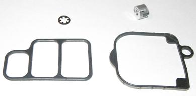
This
is a shot of a few parts that were not shown or not clearly visible in other
pictures. Upper left is the retaining
spring washer that is installed next to the return spring shaft adapter on
the valve shaft. Next, to the right
is the spring to shaft adapter. This
shot shows the offset slot where the inner return spring end sets. Also on the opposite surface is visible a larger
center slot that mates with flat surfaces on the sides of the valve
shaft at the spring end. Below that
is the rubber perimeter gasket mentioned but barely visible on the solenoid
module. To the left of that is the
special O-ring gasket that is sandwiched between the ISCV and the TB. You can see that the air outlet passages (cold
& warm) are isolated from one another.
What
may be of interest is that the two left hand coolant ports are not isolated
from one another. If you look above
at the picture of the metal body you’ll see the coolant outlet tube
is connected to the lower hole. The
coolant comes through the valve body and exits at the upper hole. No isolation is apparently needed because the
coolant only makes a “token” trip into the TB before immediately coming back
into the ISCV and passing out the lower tube to the AV.
CREDITS:
The written references I used for this article
were the 1993 Mazda MX-5 Wiring Diagram and the 1993 Mazda MX-5 Workshop Manual. I also want to thank Bill Strohm
as a considerable resource for answering questions during my troubleshooting
phase and during the writing of this article.
Also, there were numerous Miata.net forum posters that influenced my
successful outcome. Kudos to them all!
Comments from Jur:
The article on the ISCV is very clear and helpful. it helped me to get to the culprit of *very high* CO on mu 1991 NA 1.6. that was caused by clogged coolant lines that run through the ISCV and the cold idle valve. maybe you could add that as a point of interest. these cars are getting older and clogging of thes very thin lines might occur more and more.
| [Home] - [FAQ] - [Search] - [Sponsors] - [Forums] |
| [Garage] - [Clubs] - [Contact Us] - [Disclosures] - [More...] |
Copyright
©1994-2024, Eunos Communications LLC
|