
by Jim Profitt
Editor's Note: This guide gives a good overview of the timing belt replacement. Before you attempt this procedure, I suggest reading the factory manual, as well as the original Miata.net timing belt replacement guide here.
Should You Change Your Own Timing Belt?
Only you can say, but after reading this you will either be energized to get down to it, or you won't mind so much handing the job off to your mechanic. I'll tell you from the start that I did my own replacement and my Miata runs better than ever now.
After 60,000 miles you run the risk of breaking the timing belt. It may not be much of a risk, for a while, but the risk keeps getting greater all the time. I finally gave in and did the job at 70,000 miles. This is preventative maintenance. Though I've heard that the camshafts will freewheel if the belt breaks, it really looks to me like a piston can't help but smash into a valve if the belt lets go.
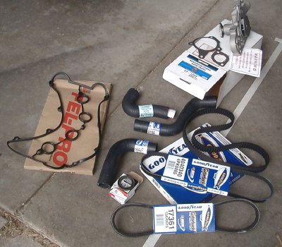
Unfortunately, there is more to be done than replacing a belt. Many of the other parts are old enough to consider replacing also, especially since most of the same disassembly must be done. I chose this list: water pump, auxiliary and serpentine belts, major radiator hoses, front camshaft seals, and valve cover gasket.
The water pump happens to be behind the timing belt, so instructions always have you remove the timing belt as a first step. This is why you may want to retire the old pump early.
It's a really good idea to get a repair manual. Take a hint and get some 'special' tools together before you go further. That's right, there's a lot of stuff that was a heck of a lot easier to put on the car than it's going to be to get off. If you can't scrounge together the special tools or if you can't work with them, then forget the rest. Fortunately, there's nothing so exotic that a reasonably handy person can't handle it. You'll need get or make camshaft seal seating tool, a crankshaft holding tool and a camshaft seal extraction tool. I'd also get some of those plastic tie straps and a tube of silicone sealant.
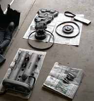
Basically, one thing unfastens or unscrews from another, pretty much like you see it in the manual. The first thing to do is gather the parts together. If dealing with after-market parts, you'll find the usual number of wrong parts, no matter how much care is taken specifying your year of Miata at the parts counter.
Parts Needed :
Collection of rubber parts: I thought they were correct at this point. Having exchanged the wrong valve cover gasket. I was to find two more of these parts incorrect.
Remember in second grade, when you'd these tests where there would be three frames with a spoon, a spoon, and a fork. You were supposed to circle the one that was different. Well, now's the time that second grade will pay off. Looking at the water pumps below, which one is different?
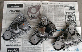
The answer is that the one on the right is not for the Miata. I didn't find out until I got it installed and found that the timing belt idler pulleys wouldn't thread into their holes. This would be really discouraging if your sole objective were to replace a leaking water pump. Apparently, the same casting is used for a number of Mazda pumps. This is not something that at least one major auto parts store (or their computer) knows about. I ordered a second pump, being even more insistent on checking the I.D., and the one that arrived still wasn't for a Miata! Your replacement pump should have a mirror type finish on the two plateaus where the timing belt idler pulleys fasten. The other pump must not be for overhead cam engines.
Note from Hiroki Miyano: In the picture, you see three water pumps. Mr. Profitt claims that two water pumps he ordered didn't fit due to smaller bolt holes. He talks about the mirror like finish in the correct water pumps. I suspect the one that fit for him was a brand new water pump as opposed to re-manufactured water pump.
I refer to Miata.net garage site often before I take on any project. I ordered my rebuilt water pump from Rosenthal Mazda dealer. I read Mr. Profitt's article as well, and thought I had a wrong water pump, because as described by Mr. Profitt the water pump bolts didn't go in using finger pressure. But then I did extensive search on forum such as "bad fit issue with water pump", "wrong water pump" etc. But nothing really came up. If what Mr. Profitt claims is actually the case, surely there should be a lot of discussion going on in the miata forum. But I couldn't find any real discussion regarding the fitting issue with water pumps.
I believe the real issue here is that the re-manufactured water pumps have a thick coat of paint, as if the water pump was submerged in a bucket of paint. The entire water pump is coated with paint including the bolt holes.
In my case, the bolt did not go in using finger pressuer. But the bolts went in fine using a wrench. I believe the thick coat of paint is making it a tight fit, but there is no issue here.
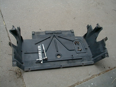
A certain amount of progress can be made before reaching the point of no return on disassembly. Start by removing the lower engine compartment cover. If you don't do anything else, this is a good time to get rid of leaves, old tools, acorns, rodents, whatever else has fallen past the engine over the last 6 years.
You'll then need to drain the radiator. This is done with a Phillips type plastic plug located at the low point of the radiator. This step is easy. Don't go further yet. You should flush the cooling system with water in order to protect the new water pump you're going to install.
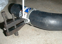
One thing you'll find is that those 'quick release' clamps on the radiator hoses are only quick releasing if you can hold about a hundred pounds of force on a snap ring while wiggling it sideways. Slip lock pliers work OK, but if the clamp is rotated with the tabs somewhere inaccessible, it's going to be a struggle to bring the tabs to a position where you can get pliers on them. A machinist's clamp or a screw type pinch clamp could be a handy tool, allowing you to lock the hose clamp in a fairly open position while you move it off the hose end and into the middle of the hose. Vise grips are O.K. too, but it takes a lot of luck to get a good latch on the clamp while not running the Vise grip handle into something. With some reluctance, I cut one of the hoses to make it easier to remove ' don't scratch the metal hose fitting. Putting the hoses back on is easier than taking them off, but the opposite is true of the clamps.
Remove the spark plug cables and write on the white firewall the order that they attach to the distributor block (3214). Then remove the plugs and save them in order if not replacing them.
The intake air plenum must be removed after the top radiator hose is off. This is easy, but you have to wiggle it some to get it out of the engine compartment.
When you start to detach metals parts, you quickly realize how lightly torqued are the nuts and screws. You should be able to remove valve cover screws with your fist over the head of the socket wrench. It's a big mistake to over-torque anything attached to aluminum. There's an order to loosening and removal of the valve cover screws, so pay attention to the manual.
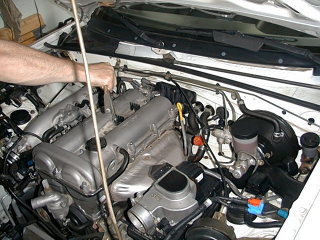
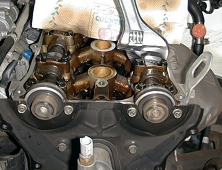
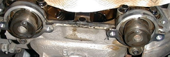
Give the cover some gentle mallet taps to loosen it. Don't be in a hurry; it isn't likely to be stuck down very hard, it just needs to get some air under the seal. Now you get to see some of the innards of your engine. If you're like me, you probably waited until it was time for an oil change, before opening the engine. So the cams won't look as shiney as the picture in the manual. We'll want fresh oil in there when it's all back together.
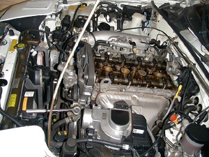
I found my timing belt to have more slack to it than I expected. This was consistent with the fact that when I recently tried to move my timing from 9 to 15 degrees, the readings seemed somewhat unsteady, making me approximate the setting. Otherwise the belt looked fine.
Now comes a process of removing the serpentine and auxiliary belts. The alternator and power steering unit will need to be loosened. I later found it handy to dismount, but not completely remove the power steering pump. There's no UN-plumbing required, the pump can just lay against the A/C compressor. There's not really anywhere for it to fall.
Take off the various covers and keep the screws with them. The water pump pulley comes off easily enough, but it has to be kept from turning. I wedged a grippy block between the pulley and the water intake tube.
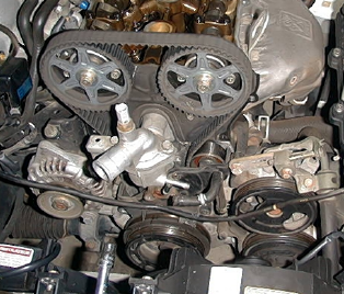
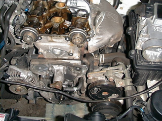
Here you can see the outer timing belt covers, accessory belts and the water pump pulley have been removed:
The crankshaft pulley is easy to remove. It's held on with four screws. By this time, you've got a number of parts around. Keep everything orderly and clean.
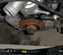
Removal of the crankshaft pulley will reveal the timing belt retaining disk and the big crankshaft screw, which you will have fun with soon enough.
The timing belt retaining disk is behind the pulley: it has an alignment pin that should be at about 12 o'clock.
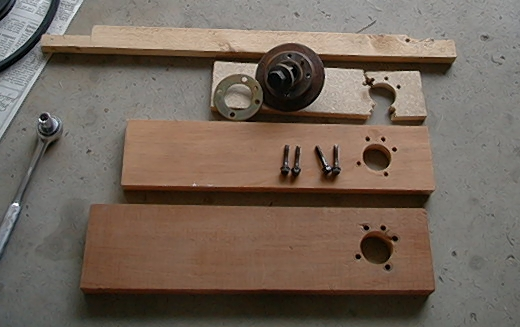
A tool can be made to hold the crankshaft while the big center screw is loosened. The tool will use the four screw holes on the retaining disk and will allow for the alignment pin. I went through several tools before I got one strong enough to serve. Don't bother with particle board or flimsy plywood. The choice is metal, using the pulley screws, or thicker hardwood, using the screws from the top belt cover.
The timing belt retaining disk has a pin in it, which should be oriented up. The strengthening ring from the pulley can be used to draw the pattern of the pin and the boltholes on your tool. I found the screws from the larger belt cover to fit the holes in the timing belt retaining disk and to go through ľ' hardwood. The arm of the tool should hang about 7 to 8 o'clock, so it does not collide with other parts. I used a car jack to take up the slack and prevent rotation of the tool while I used a long arm ratchet on the 21mm crankshaft screw. If you don't have a long breaker bar or socket wrench, here's the perfect excuse to get one. You hope to get something out of this ordeal, right? I found a flex head ratchet to cost only slightly more than the same size breaker bar, and it's much more versatile.
Here are some various hold tools of increasing success. The gold color pulley-strengthening ring is used to trace screw hole patterns. Notice the hole for the alignment pin.
Before removing the timing belt, get the timing marks on the cam sprockets lined up. Your manual should be very clear about the orientation of the cam sprockets. The 'E' and 'I' guide marks at about 4 and 8 o'clock positions on the cam sprockets will align with the arms of a 'Y' shaped mark embossed on the steel back plate. It's the small lines on the outer edge of the sprockets that are the real marks, not the 'E' and 'I.' Do yourself another favor- mark the belt with white pencil where the top sprocket marks, near 'I' and 'E,' touch the belt. Put a similar mark on the belt and the crankshaft drive sprocket. This will let you use the old belt to mark the new belt, and should help alignment to be tooth-for-tooth correct. It's O.K. to remove the belt idler pulleys. Manuals don't seem to mention this, and I didn't realize it until later, but the idlers are going to come off when the pump is replaced anyway, and it takes a lot of strain off the belt. I also removed the idler pulley spring, rather than have it pop off. If you've replaced a drum brake spring before, it's the same kind of thing. After removing the belt, the camshafts will move a bit on their own as the valve spring pressure presses on the cam lobes. Don't worry about it. The camshafts have hex sections that allow them to be wrenched to better positions. The crankshaft drive pulley comes off easily, even though it's keyed in place. There isn't much reason to remove it, but if you do, don't let it fall on the concrete floor.
The camshaft sprockets have to come off before the seals and water pump can be replaced. Use a wrench on the hex portion of the camshaft to hold the cam still while loosening pulley screws. Just don't let the wrench contact the aluminum casing; that needs to stay flat and chip/dent free!
Removing the backplate gives access to the camshaft seals. Those things are really stuck firmly in place. It's tricky getting the old ones out. I think a good tool could be fashioned from a small steering wheel puller, but I did it a riskier way. Whatever you do, don't scratch the walls of the well that a seal sits in. If it leaks oil, your new belt won't last long at all. If you plan this step, get the installation tool ready before you start. . The tool for seating new seals is a 2-3 inch section of 1-5/8 inch PVC pipe. The wall is about ÂĽ inch thick and one face can be sanded smooth. It's fairly rugged stuff, and will stand up to any reasonable amount of 'encouragement' that may be needed to set the new seals.
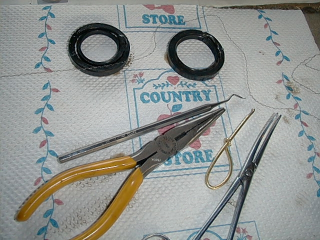
Inside the rubber seal is a circular spring to snug it to the camshaft and a strong ring of steel with a lip to hold it in its well. I used a dental tool to pierce the rubber and hook the inner spring. Pulling it out unzips the tired rubber around the camshaft and leaves the outer portion. A cross section of the hidden steel ring would show an 'L' shape, where the small leg of the 'L' provides surface for pressing the seal into its well. I used pliers to pull a small section of this lip flat, from an 'L' to an 'I' shape. I then used an old screwdriver and carefully tapped toward the camshaft to make a bend in the ring. This slightly decreased the diameter of the ring and made seal removal practical. My manual suggested using two wood screws in the face of the seal to fashion pull handles. There's no way that idea will work. Rather than use steel tools, I bent and filed a piece of soft brass wire so it would serve as a hook, but would be smooth on any part that might accidentally contact aluminum.
Getting the old seals out takes some care, here are some tools used in the removal:
Check the depth of your new seals so the old ones can be compared. This gives an idea of how far the new one needs to travel to reach the base.
Once the old seals are out, clean the well with Q-tips sprayed with brake-part cleaner. The new seal needs a bit of oil on the lip to survive the trip into the well. Start inserting it gently to assure it doesn't get cocked in the well.
If the water inlet tube has not been removed yet, do it now. It seals with a thin rubber ring, so don't let it get away. The water pump is now accessible.
This part is not too hard. The pump will be stuck in place after the screws are removed, but it shouldn't take too much effort to pry it away from its old gasket. The part of the block underneath is iron. Aluminum, brass and plastic tools can be used to help peel off old gasket material. Get the surface clean and dry.
Follow manual directions to silicone seal the new gasket and torque the new pump in place. The inlet tube, back plate, and cam sprockets can be reinstalled now.
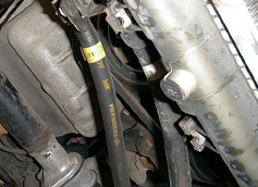
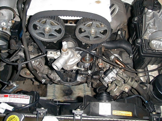
Now is the moment you've been waiting for: installing the new timing belt! Install the belt idler that does not have adjustment. Use the wrench fitting on the left camshaft to get the teeth lined up with the marks you cleverly made at the beginning. The engine's left side of the belt needs to be fairly tight, so you should use a wrench on the hex fittings of the camshafts to add some tension. All marks should line up properly. If someone is holding that wrench on the camshaft for you, you can wiggle the adjustable idler pulley into place and temporarily snug it in place to hold the belt where it belongs. The right amount of tension will be applied by the tensioning spring, once it's re-installed and the pulley mounting screw is loosened a bit. Tightening it to the specified torque finishes setting the belt. The manual described the process of hand cranking the engine some to make sure movement is smooth and marks line up again.
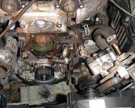
The belt has been mounted with correct alignment at this stage but the belt-tensioning pulley has not been set:
The remaining re-assembly is an easy reversal of the process. A new valve cover gasket is a good idea. Instructions in your manual should have you clean the old seating channel and prepare it with silicone. The head surface gets no silicone, except for six small spots where the rubber gasket makes a 90-degree vertical turn over the camshafts.
I found the new radiator hoses to have the correct bends, but they were up to 2 inches too long. Trimming to size was easy with a razor knife. Working with those quick-release clamps is not so easy. The two tricks I applied were to squeeze the clamps all the way open with slip-lock pliers then hold them with a machinist's clamp, or one of those locking, plastic ties.
The moment of truth, of course, is when the engine does (or does not) come back to life. Mine was reluctant to start. Mostly because of being open to the elements so long, I think. But also because the timing with a new belt is somewhat different than with a tired old belt. That was easy to set to the desired 15° BTDC. If the timing is off very much, you may have mounted the timing belt a tooth off. This is probably not enough to cause a piston and valve collision (you checked for that in the manual cranking step), but it will make the car run very sluggishly. There's only one corrective action, and to be kind, I won't mention it.
There is a great deal of satisfaction in successfully completing a job like this, and it will bring you in closer rapport with your machine. By now you should have an idea of the down side: a certain level of risk and bother. Most people will give this job to the experts, and if the price is halfway reasonable (after all, you now know they are going to put some effort in this) that is the correct decision. For those that decide to take matter in their own hands- good for you!
| Back to the Garage |
22 June, 2008 |
| [Home] - [FAQ] - [Search] - [Sponsors] - [Forums] |
| [Garage] - [Clubs] - [Contact Us] - [Disclosures] - [More...] |
Copyright
©1994-2024, Eunos Communications LLC
|