|
Fiamm Air Horn Installation Doug
Thomson I didn't really plan on putting this installation on the web, so I only took the pictures after the job was done. I originally bought the Crazy Red kit, but I found Red's plan was beset by a few problems. First I didn't like overloading the brake light/horn circuit by installing a 20 amp fuse instead of the stock 15 amp - I did it, but it just sat there eating away at my conscience. Second, Red's horn mounting location resulted in my horns freezing up as soon as the weather got cold, and my nice loud Italian horns were sounding out tiny mmmmrrrfff's ... didn't like that. Third, with the horns mmmmrrrfff'ing, my horn was useless ... I wanted a backup. So, I decided to rewire the horn using a separate relay, relocate the horns and compressor to the engine compartment where they would stay clean, dry and warm, and rewire the stock horn in parallel with the Fiamm's. The job was simple, cost under $20 ... I was able to use scraps of aluminium I had lying around to build a bracket for the compressor. I used existing tapped holes to attach everything with 10mm bolts. |
| Materials: |
|
|
Tools |
|
Click
on the thumbnails to see full sized image.
The link opens a new window. Close it to return here
I didn't give any thought to putting this project on my web site
| A Few Pictures: | |
| Wiring diagram. Make sure that you check the wiring diagram on the relay that you buy. This diagram is typical of most relays that I have found.Click on the thumbnail to get one you can actually read. |
 |
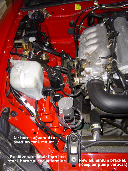
| Overview of the passenger side of the engine compartment - no the washer tank isn't missing. On Canadian cars it is on the driver's side. These mounting locations work for me because I don't have ABS ... if you have ABS you will have to move the in-line fuse. If you have a Thompson oil filter relocation kit, you will have to find another location for the compressor and the horns. Just keep in mind that the compressor must be mounted vertically. |
 |
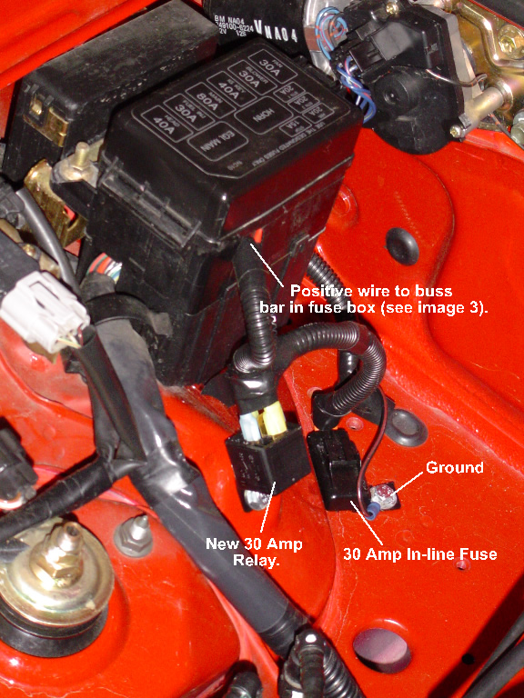
| Here's a picture of the 30 Amp relay and 30 Amp in-line fuse. I like to insulate my electrical connections with shrink tubing wherever possible. As you can see I also like to use Poly Vinyl Split Loom to enclose all the wires. |
 |
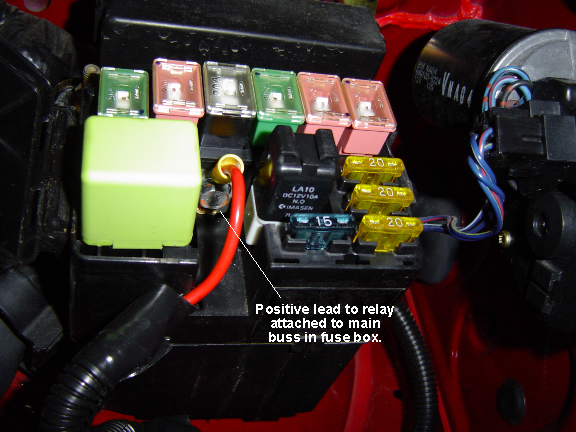
| Don't try to tie into one of the fuses in your fuse block. Instead, simply tie into the main buss. |
 |
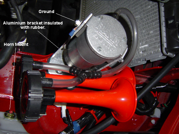
| A close up of the mounting brackets for the compressor and the horns. |
 |
|
|
|
| Back to the Garage |
8 April, 2006 |