Note: These instructions are for a '99 Miata with power windows and an automatic passenger's side door lock. If you have manual windows, you'll need to remove the window crank. If you don't have automatic passenger's side door lock, you'll need a kit with two actuators instead of one.
One of the things we loved about the M2 Miata is the automatic door lock that comes with the Popular Equipment Package. But we soon realized it was just not quite "there" - you still had to use the key on the driver's side. And if you used the key on the passenger's side, it didn't open the driver's side automatically. Why didn't Mazda have lock actuator solenoids on both sides? We figured Mazda would probably make it an option or part of a more "premium" package, but they didn't. So we were excited when Duetto Motors LLC began selling a keyless remote kit to upgrade the '99.
Well, we bought the kit from Duetto, but being a brand new offering, they hadn't yet customized the kit for Miatas. It was a generic power lock kit and we were left pretty much to our own devices to come up with an appropriate way to install it. We were told that they were working on instructions specially designed for the Miata and they'll probably have them by the time you order the kit. But we were on our own.
The tools you'll need:
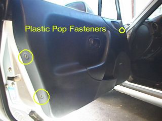
 Remove the three pop rivets from the
door trim panel. Two are located on the side furthest from the hinge. The third is located
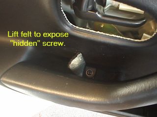
near the vent window. Remove the Phillips head screw from the door handle. There is also a
hidden Phillips head screw located under the felt on the door handle. Lift the felt to
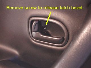
expose the screw and remove it. Remove the third Phillips head screw from the black
plastic door latch bezel. To remove the bezel, pull the latch all the way out and remove
bezel.
Remove the three pop rivets from the
door trim panel. Two are located on the side furthest from the hinge. The third is located
near the vent window. Remove the Phillips head screw from the door handle. There is also a
hidden Phillips head screw located under the felt on the door handle. Lift the felt to
expose the screw and remove it. Remove the third Phillips head screw from the black
plastic door latch bezel. To remove the bezel, pull the latch all the way out and remove
bezel.
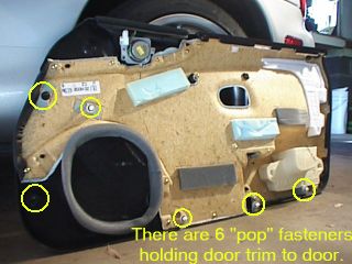
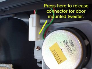
To remove the door trim, grasp the bottom of the trim and yank it toward you to pop out the fasteners. There are 6 fasteners in various spots on the trim. After all 6 have popped loose, you can gently lift the trim panel up to release the hooks at the top of the door. If you have the Bose door mounted tweeters, you'll have to remove the connector before pulling the trim completely away.
After removing the door trim, you will see the plastic vapor barrier that covers the entire door area. Take extra caution not to tear this plastic trim! The vapor barrier is important! You'll have to peel down the vapor barrier to expose the lock rods and pivot - this is the area where you'll be installing the actuator. The black goopy stuff that holds the plastic to the door is the most tenacious stuff ever invented! Don't get it on your clothes or on the upholstery! You'll never get it off!
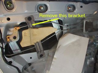
 Remove the flimsy metal bracket that
has the stiff foam permanently molded to it. We don't think it serves any purpose anyway.
In fact, we suspect this is the spot where Mazda would have put a remote actuator
if they had offered it as an option. Anyway, throw that piece in your box of
spare parts you keep in the basement that contains stuff like OEM shift knobs and tie down
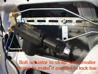
brackets. You'll then need to mount the strap (included with actuator kit) to the door.
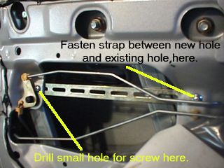
Since the important thing is to ensure that the actuator is mounted parallel to the lock
rod, there are no existing holes that we could use to mount the strap. We settled on a way
of doing this by drilling a single hole just above the pivot point and fastening the strap
between this new hole and the existing hole on the opposite side of the opening (see
figure.) The screw on the right must be no longer than about 3/8" or it will
interfere with the window mechanism. The one on the left can be about 1/2" long.
Remove the flimsy metal bracket that
has the stiff foam permanently molded to it. We don't think it serves any purpose anyway.
In fact, we suspect this is the spot where Mazda would have put a remote actuator
if they had offered it as an option. Anyway, throw that piece in your box of
spare parts you keep in the basement that contains stuff like OEM shift knobs and tie down
brackets. You'll then need to mount the strap (included with actuator kit) to the door.
Since the important thing is to ensure that the actuator is mounted parallel to the lock
rod, there are no existing holes that we could use to mount the strap. We settled on a way
of doing this by drilling a single hole just above the pivot point and fastening the strap
between this new hole and the existing hole on the opposite side of the opening (see
figure.) The screw on the right must be no longer than about 3/8" or it will
interfere with the window mechanism. The one on the left can be about 1/2" long.
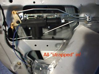
Ideally, it would have been nice to simply bolt the actuator to the strap. No such luck - if we do that, it sits too high and interferes with the lock rod. So we needed to position it about an inch lower than the strap itself. (No, we couldn't simply mount the strap an inch lower - there was no place to fasten it.) To do this, we decided to use two shorter metal straps (about 2" long). One end of the shorter straps bolts to the horizontal strap. The other end gets bolted to the actuator. You'll have to fool around with positioning of these straps in order to achieve a final position which leaves the actuator low enough to clear the rods, yet still parallel to the rod. Also, be sure to use nuts with nylon locking inserts so the screws don't eventually vibrate loose.
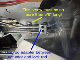
 Now that the actuator is properly
positioned, you can connect it up to the lock rods. Cut the actuator rod (supplied) to an
appropriate length and place it through the eye of the door lock actuator plunger. Using
the Allen key, tighly fasten the rod adapter supplied with the kit between the lock rod
and the actuator rod. A bit of thread lock compound on these Allen screws wouldn't be a
bad idea either.
Now that the actuator is properly
positioned, you can connect it up to the lock rods. Cut the actuator rod (supplied) to an
appropriate length and place it through the eye of the door lock actuator plunger. Using
the Allen key, tighly fasten the rod adapter supplied with the kit between the lock rod
and the actuator rod. A bit of thread lock compound on these Allen screws wouldn't be a
bad idea either.
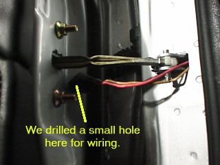
You'll need to drill a hole (about 3/8") in the door near the hinge to pass the wires through. If you can figure out a way to use the existing wire tube, power to ya'. We couldn't. We drilled. Use a rubber grommet to protect the wires from the rough edges.
Cut two lengths of wire about 1 meter long, and splice them to the actuator leads. Run the wire carefully between the vapor barrier and the door metal, across to one of the openings, and out to hole you drilled. We then passed the wire into the car at the attachment point for the door travel limiter. There's probably a better way to do this, but we were getting tired of drilling and it seemed like it would be OK. We recommend coming up with a better way of getting the wires from the door to the car. (See Tom Blough's writeup below.) Here's a writeup Duetto sent us, but we're not sure it's applicable to the '99:
 If you look into the left side of the body
(can be seen under the dash with a light) where the wiring comes through, the plug can be
seen. There are a couple of small green tags on the plug. Push the green tag with a small
round instrument (eg coat hanger wire) and the male end of the plug will come loose from
the gap between the door and body. Pull the plug out. The female end still sits in the
side of the car body. There is a clip in top and bottom of that female end that if pushed
down will release this part of the plug outward. If you look at the two parts of the plug,
there is a space at the top through which the wires can be pulled. On the car end
(female), a small hole can be drilled to pass the wires back into the car from the
accordian tube (run the wires through that to exit at the male end). The wires can then be
pulled inside the car yet stay in the accordian tube. The female side is then reinserted,
the male end is plugged ito it, and the boot from the accordian tube is placed around it
to give a seal.
If you look into the left side of the body
(can be seen under the dash with a light) where the wiring comes through, the plug can be
seen. There are a couple of small green tags on the plug. Push the green tag with a small
round instrument (eg coat hanger wire) and the male end of the plug will come loose from
the gap between the door and body. Pull the plug out. The female end still sits in the
side of the car body. There is a clip in top and bottom of that female end that if pushed
down will release this part of the plug outward. If you look at the two parts of the plug,
there is a space at the top through which the wires can be pulled. On the car end
(female), a small hole can be drilled to pass the wires back into the car from the
accordian tube (run the wires through that to exit at the male end). The wires can then be
pulled inside the car yet stay in the accordian tube. The female side is then reinserted,
the male end is plugged ito it, and the boot from the accordian tube is placed around it
to give a seal.
1. Disconnect the existing connector. Above where the accordion tube enters the shell is a small raised circular area. Inside of this is a small green plunger. Using a small flat bladed screwdriver, pull this plunger out as far as it will go (about 1/4"). This should allow the connector to disconnect.
2. Peel the rubber dust boot back from the white plastic connector.
3. Now, let’s remove the connector from the body. Take 8 years of yoga lessons to enable you to look up under the dash at the inside of the connector. Grab the wire bundle coming from the connector and push slightly. While still pushing from the inside, use a small screwdriver on the outside and press down on the release in the middle top of the connector. There is also a release in the middle bottom, use this to free the bottom of the connector in the same manner. Push the connector out towards the door using the wires until the top of the connector is out. Tilt the bottom of the connector towards the body and push it inside. You need to tilt the connector enough to let the lip on the bottom of the connector clear the opening. Now with the connector still tilted, push it the rest of the way inside making sure the lip at the top clears the opening. Once the connector slips inside, pull it down below the dash.
4. Looking closely at both halves of the connector, you will see two unused spaces. This is where we will be installing the contacts for our wires. Since it is impossible to find the OEM contacts, we will use Molex contacts available at Radio Shack. You can’t buy the contacts separately, but you can get all you need with the 2 position Molex connector for $0.99. The Radio Shack PN is 274-222. Below are pictures of both halves of the connector with the new contacts installed:
Door half of connector
Body half of connector
5. To fit the contacts into the connector use a 0.125" (1/8") drill bit to drill out each of the four contact locations, two in each half of the connector. Drill all of the way through being careful of the existing wires when you break through. Let the bit seek out its own position when going through the plastic.
6. On the door half of the connector only, we need to counterbore the two holes 3/8" deep using a 0.156" (5/32") diameter drill bit. Measure 3/8" back from the tip of the bit and wrap a piece of tape around the bit at this point. Now re-drill each hole slowly, going only as deep as the tape. This counterbore allows the female contact to expand when the male contact is inserted.
7. Run your wires from the actuator through the accordion hose but not through the connector yet. Attach a female Molex contact to each wire.
8. Now using a small screwdriver or other suitable object, press each contact, starting from the wire side, into the holes until the end of the contact is flush with the opposite mating surface of the connector.
9. Attach a male Molex connector to the end of each of the two wires going to the keyless control box. Press these contacts into the car half of the connector starting from the wire side until the spring tangs on the contact just pop out on the other side.
10. Now, apply a small dab of epoxy on the wire side of each new contact to the wire securely in the housing.
11. Reassemble the rubber dust boot to the door side of the connector, reinstall the body side connector into its cutout, and reattach both halves. Press in the green pin after the halves are mated.
One additional connection not mentioned in the Garage write-up has to do with the parking light flash feature. If you want your parking lights to flash twice when activating the Keyless unit with the remotes, then make the following connection.
Remove the two Phillips screws holding the panel below the steering column and remove the panel. Attached to the column, is a large black connector. Locate the light green wire coming out of this connector and connect the yellow lead from the keyless control unit to it. That's it. Your parking lights and your instrument lights will now flash twice whenever the control unit receives a signal from the remote.
OK, so now have the wires from the actuator sitting in the footwell someplace, right? Yes, of course you do.
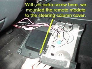
We mounted the keyless entry unit (KEU) to the steering column cover. There seemed to be a ton of space there, so we filled it. Using one of the existing screws on that cover used to hold that hunk of useless metal on one side, we added a second screw on the other side which conveniently had a spot to screw into without drilling through the cover. Alternatively, you could use double sided tape. Or find another location for it. It doesn't really matter where you put it.
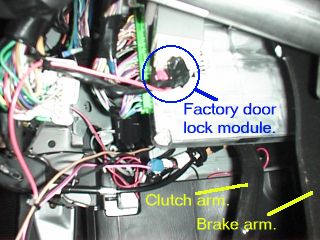
Connect the White, Pink, and Black wires to a good ground. We soldered them together near the connector and ran a single ground wire to a bolt on the chassis in the footwell area. Install a fuse on the red wire, and connect the Green and the Red wires from the KEU to a 12 volt source. Be sure not to use a source that requires the ignition to be turned on. We wired it into the existing door lock circuit of the car. The door lock circuit can be accessed by tapping into the factory door lock module. Locate the module in the footwell (see the photo). There is a connector on the bottom of it with 6 wires. The orange wire is the door lock circuit. We used a tap to connect the KEU wires to the orange wire. Finally, connect the White/Black wire from the KEU to the Green wire from the actuator. Connect the Pink/Black wire from the KEU to the Blue wire from the actuator.
Extend the antenna wire from the KEU and hide it someplace under the dash. We left ours coiled up which limits the range, but that was the way we wanted it to work.
Follow the instructions that came with the kit to teach the KEU the remote codes and test the system to be sure it works. If necessary, adjust the actuator rod adapter or the actuator positioning until everything operates correctly.
Once you're satisfied it works, replace the vapor barrier, re-install the door trim and put everything back the way you found it!
| Back to Garage | 07 January, 1999 |