An air bag is an explosive device, and should be given the respect of one. These directions are for information only. Removal of the steering wheel involves working with the airbag. This procedure should only be performed by a qualified mechanic. The author, Miata.net, Mazda, the Miata Club of America, and Eunos Communications are not responsible for any damage or injury caused by use of these procedures.
The following was gleened from instructions developed by frequent Miata.net contributors
Lester Seal and Aaron Tachibana
Blame Bob Crawford for editing errors or confusion
Photos by Dr. Bob Fisk.
What You'll Need:
Remove the negative cable from the battery (10mm wrench).
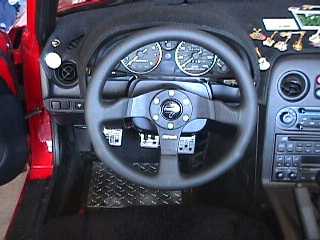
Remove the panel under the steering wheel (2 Philips screws on the bottom edge).
Disconnect the clock spring connectors (large blue and orange connector). First the orange connector has to be disconnected (there is a clip on the side), then the blue connector is disconnected (the clip is in the middle and is covered by the orange connector when connected).
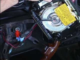
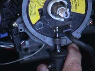
Put key into ignition switch and unlock steering column so the steering wheel can turn. Locate and remove the 4, 10mm nuts on the back side of the steering wheel (these nuts hold the air bag to the steering wheel). Lift the air bag off the wheel. You will notice it has a cord attached between it and the wheel, loosed the cord from the steering wheel and remove.
Look carefully and you can see the screws protruding from the back of the wheel. Also note the orange and blue connectors. Pull the orange and blue connector from the clip in the wheel and disconnect (the same way as the clock spring connector). Put air bag to one side.
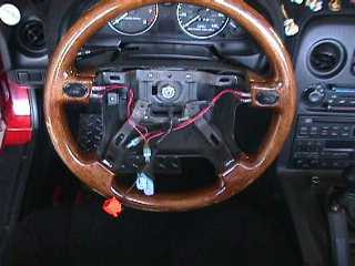
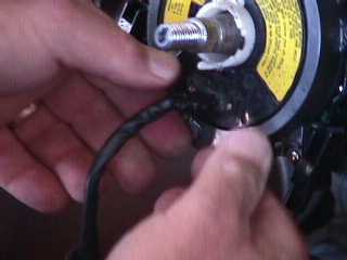
Center steering wheel, and mark the stud of the shaft (inside of the nut) with the magic marker so you know where the straight ahead position is when the wheel is removed (I place a mark from the dimple in the center of the shaft, vertically to the edge of the shaft). Remove the 21mm nut. Remove the wheel. A rocking motion with one hand opposite the other on the wheel, pulling toward you at the same time should get it loose.
Next ... start the modificationsOnce you have removed the old steering wheel and air bag...stop...do NOT throw anything away. You will be modifying the existing parts. The work is nothing dramatic but usage of the stock parts is imperative. Mazda does not sell the individual components in the steering column...you have to buy them all in a complete kit. This is expensive, and not necessary if you follow the instructions.
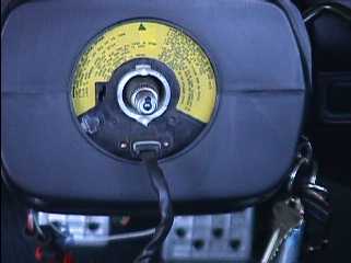
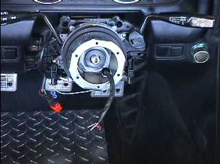
Once the wheel is removed you will see the clock spring connector. Remove the four screws that hold together the black cowling surrounding the clock spring and steering hub. Please note the white turn signal devise with pins at 12 and 6 o'clock and the mark placed at 12 o'clock on the steering hub.
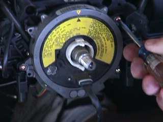
Note the 12 o'clock position marked on both the clock spring and outer housing. Also note the rectangular "bumps" on the top and bottom of the white signal device. You'll be modifying these "rectangular bumps."
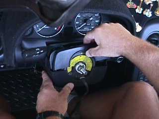
Undo the screws as shown and lift out the clock spring. There should be enough slack in the wires to let you pull it out forward over the hub and just let it dangle. My wires were very tight, but with some gentle encouragement, they pulled enough to remove the clock spring.
You have now exposed the turn signal canceling device, the white plastic thing that has two opposing locator pins at 12 and 6 o'clock positions. Take a permanent felt tip marker and place a mark on one side so you'll know how which way to put it back in. I marked on the right with a Sharpie marker.
Take out the clock spring connector. You'll notice that there is a three wire lead and a large multi-connector attached. On the end where the large multi-connector is, cut it off with a pair of wire snips. You will not need the multi-connector portion, but you will need to utilize the wires.
Next on the end of the wire that attaches to the clock spring connector, there is a rectangular black connector surrounding the wires and is attached to the clock spring connector with two very small brass rivets. (Clearly visible above)
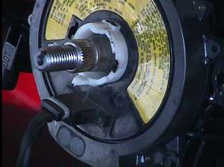
This is a white plastic thing that has two opposing locator pins at 12 and 6 o'clock positions. This is the turn signal canceller. Take a permanent felt tip marker and place a mark on one side so you'll know how which way to put it back in. You'll soon be modifying it. Also, you'll see to raised portions at 12 and 6 p.m. running from front to back. With the unit together, draw a small line on the white unit where the clock spring face meets the white protrusions.
After removing the clock spring connector you'll see the exposed white turn signal canceller. This is pressed into the steering column. Grab it with your fingers and pull out gently. It should just pop out. Now you know why you marked the orientation of the turn signal canceller.
Take a Dremel tool grinder and carefully grind an approximate 1/4" notch behind the scribed felt tip marks you have made on the turn signal canceller. Be careful not too grind the tab off or go all the way through. you want to grind just enough on both of the clock spring connector mounting tabs on the turn signal canceller so when you reinstall it the clock spring connector will now rotate 360 degrees around the turn signal canceller. This is very important. You may have to fit and refit the assembly to get the correct notch clearance between the turn signal mounting tabs and the clock spring. It sounds difficult, but when you have the items in hand you'll understand what clearance is required.
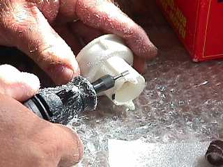
Here's where one needs to be careful. Using a small saw such as a fine toothed coping saw or Dremel tool used lightly, gently cut the outer casing off of the connector, cutting as close to the clock spring connector body as possible. (See above) The cuts should be parallel to the face of the clock spring. Cut very slowly and not too deeply. About 1/16" should do it. There is an inner connector inside the housing that you do not want to cut. Be careful to not cut into or cut through this portion of the connector. You are merely trying to remove the outer connector casing so you can reduce the physical size of the connector because you are going to place this connector through a hole in the hub adapter.
After you cut the outer connector housing off you will expose the inner black wire connector housing and three wires protruding from the clock spring connector. Wrap a small piece of electrical tape around the housing and wires. Keep it tight and wrapped small, remember the reason you cut off the outer connector housing was to make the connector as small as possible without jeopardizing structural rigidity.
Once all has been done, reassemble the unit. put the turn signal canceller in (it just snaps into place...remember the mark you made indicating the original orientation). Follow the instructions on the clock spring connector as to how to orient the internal spring. It's self explanatory, and written in black lettering over a yellow background on the clock spring connector itself. Secure the clock spring connector to the steering assembly.
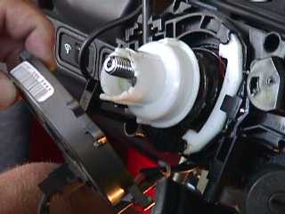
Now comes the modification of the hub adapter. It is Momo part number #5702 and is shown mounted to the steering column. Take the hub adapter and turn it over. You will notice that there is a brass and black plastic ring around the bottom opening. Simply pry this ring off and discard it.
You will now notice an approximate ỳ" hole in the 5 o'clock position on the hub. Take a 1/2" drill bit and drill out the hole. Once you have done this, chamfer the hole so that it is slightly out of round ... a little oval works well. (Note the hole in the adapter, above). Using this methodology removes the necessary amount of metal so that the connector can go through, yet leaves as much of the hub adapter base as possible for structural rigidity. This is the hole that the wires from the clock spring connector are going to protrude from. Now you understand why you removed the outer connector on the clock spring connector wires.
Feed the wires from the clock spring connector through the hole in the hub adapter (note wires coming through enlarged hole in the 5 o'clock position), and mount the adapter to the steering column. It may take a couple of tries as there are the two locator pins sticking up from the turn signal canceller that you need to insert into the bottom of the hub adapter. Careful...do not use brute force. The splines on the hub adapter and the steering column are fine thread, and it takes patience to line everything up right. Once you've got the adapter on take the green and wire (this is the power lead for your horn) and attach an electrical slip couple to the end of the it. Then attach it to the horn button. Run a ground wire from the negative pole on the horn button and afix it to the post on the shiny hub ring that goes between the hub and wheel.
The other two wires attach together to complete the air bag circuit ... the air bag light will keep blinking unless you place a 3ohm ỳw resistor in the wiring harness.
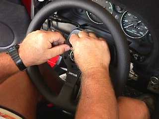
Now assemble whatever Momo steering wheel you have following the manufacturers instructions.
And there you have it!!
| Back to the Garage | 07 April, 2001 |