Installing Power Door Locks in the Miata
by Ben Lawrence (blawrence@metrolink.net)
With a section on Wiring
Relays by Patrick Whitenight
How do they work?
 Power
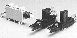
door lock actuators such as these work by using a small electric motor with a geared
spindle to drive a plunger arm forward or backward. The direction of the plunger is
determined by the polarity of the DC power supplied. By coupling the plunger arm to the
existing rod within the car door which moves the door lock mechanism, the actuator can
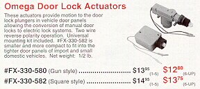
lock or unlock the door. Two different models are shown here, a square "compact"
style on the left and a pair of "gun" style actuators on the right.
Power
door lock actuators such as these work by using a small electric motor with a geared
spindle to drive a plunger arm forward or backward. The direction of the plunger is
determined by the polarity of the DC power supplied. By coupling the plunger arm to the
existing rod within the car door which moves the door lock mechanism, the actuator can
lock or unlock the door. Two different models are shown here, a square "compact"
style on the left and a pair of "gun" style actuators on the right.
What's in a kit?
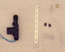 A typical
power door lock kit will provide a door lock motor, mounting hardware, a connecting rod,
and a coupling block. Kits like this can be purchased for under $10 and you will need one
for each door. Some more expensive kits provide 2 or 4 sets of actuators and hardware
along with wire and a switch suitable for mounting in the door or center console. In this
photo the connecting rod has already been bent into a lazy "Z" in preparation
for mounting in the Miata.
A typical
power door lock kit will provide a door lock motor, mounting hardware, a connecting rod,
and a coupling block. Kits like this can be purchased for under $10 and you will need one
for each door. Some more expensive kits provide 2 or 4 sets of actuators and hardware
along with wire and a switch suitable for mounting in the door or center console. In this
photo the connecting rod has already been bent into a lazy "Z" in preparation
for mounting in the Miata.
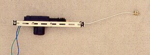 To assemble the kit
fasten the lock motor to the mounting strap using two of the sheet metal screws. The
remaining two screws and speed clips will be used to mount the strap to the door. I
substituted stainless steel sheet metal screws for the ones provided to make sure they
would not rust. The connecting rod is attached by feeding it through the eye at the end of
the actuator arm. One end of the rod is pre-bent 90 degrees and has a small head which
keeps from slipping out of the hole. The coupling block is a small brass block which ties
the connecting rod to the existing door lock rod and is held in place through the use of
two small set screws.
To assemble the kit
fasten the lock motor to the mounting strap using two of the sheet metal screws. The
remaining two screws and speed clips will be used to mount the strap to the door. I
substituted stainless steel sheet metal screws for the ones provided to make sure they
would not rust. The connecting rod is attached by feeding it through the eye at the end of
the actuator arm. One end of the rod is pre-bent 90 degrees and has a small head which
keeps from slipping out of the hole. The coupling block is a small brass block which ties
the connecting rod to the existing door lock rod and is held in place through the use of
two small set screws.
Mounting it in a Miata
To remove the interior door trim panel first take off the armrest
(if you have one) by removing the three mounting screws. Remove the single screw holding
the door handle cup in place and slide the cup off of the handle. If you have manual
windows remove the crank handle. This is held in place with a retaining clip which you can
usually remove by wiggling the edge of a rag behind the handle. Now pop out the snaps all
around the bottom and both sides of the panel and lift it straight up to free it from the
door. These instructions may vary slightly between model years.
Behind the trim panel is a sheet of plastic material held on with a
tar-like substance. You will probably have to remove this sheet completely while you work
on the door. The tar can make a big mess so be careful. TIP: Cover the tar with
a two inch strip of plastic kitchen wrap all the way around while you have the plastic
sheet off.
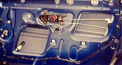 Inside the door of a Miata the locking rod is the upper of the two rods
shown, connecting the standard sliding lock button on the door handle to the lock
mechanism. The lower rod connects the inside door handle to the door latch. The lock
actuator must be mounted parallel to the motion of the lock rod, preferably at the same
height.
Inside the door of a Miata the locking rod is the upper of the two rods
shown, connecting the standard sliding lock button on the door handle to the lock
mechanism. The lower rod connects the inside door handle to the door latch. The lock
actuator must be mounted parallel to the motion of the lock rod, preferably at the same
height.
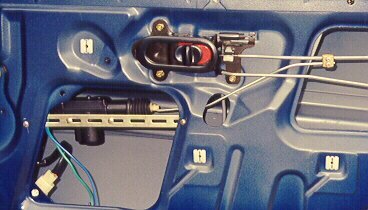 The compact style
actuator would probably have fit in the upper opening directly behind the locking rod
(ideal), but the gun style was a little too long for this location so I mounted it in the
lower opening. Drill a hole in the door on each side of the opening, place the assembly
inside the door, and mount the strap using the sheet metal screws and speed clips. You may
decide to use nuts and bolts instead, but try to get stainless steel if possible. Because
the motor is mounted lower than the locking rod the connecting rod must be bent into a
"Z" shape in order to make the connection. The rod is fairly rigid, and will
maintain this shape without deforming during use. Note that the motor is mounted inside
the door and the connecting rod must pass through the small oval opening below the handle
to mate with the lock rod, which is outside the door.
The compact style
actuator would probably have fit in the upper opening directly behind the locking rod
(ideal), but the gun style was a little too long for this location so I mounted it in the
lower opening. Drill a hole in the door on each side of the opening, place the assembly
inside the door, and mount the strap using the sheet metal screws and speed clips. You may
decide to use nuts and bolts instead, but try to get stainless steel if possible. Because
the motor is mounted lower than the locking rod the connecting rod must be bent into a
"Z" shape in order to make the connection. The rod is fairly rigid, and will
maintain this shape without deforming during use. Note that the motor is mounted inside
the door and the connecting rod must pass through the small oval opening below the handle
to mate with the lock rod, which is outside the door.
Place the coupling block over the end of the connecting rod and
tighten the set screw. Unlock the door, retract the lock motor plunger all the way, and
attach the coupling block to the lock rod and tighten the set screw. Connect the power
wires from the motor to your alarm system as directed and you're all done!
Alternatively, you may install a momentary contact DPDT (Double Pole
Double Throw) switch somewhere in the cockpit and wire it so that the lock motor receives
power with one polarity when the switch is closed in one direction and the opposite
polarity when the switch is closed in the other direction. When the switch is at rest the
motor should not have power.
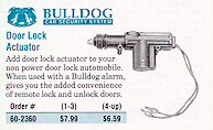
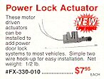
Sources for Lock Actuators
 MCM Electronics
650 Congress Park Drive
Centerville, OH 45459-4072
1-800-543-4330
Parts Express
340 E. 1st Street
Dayton Ohio 45402-1257
1-800-338-0531
Sound Conceptions
177 Main Street
Ft. Lee, NJ 07024
NetMarket Shopper's Advantage
An online shopping service - look under Car Security in the Car Accessories area
by Patrick Whitenight pwhitenight@yahoo.com
Ben Lawrence wrote an excellent article on the mechanics of
installing power door locks in a Miata, so I will only discuss the electrical wiring part
of the job. If you have a car alarm with built-in relays (like Ben has) then you can wire
your door lock actuators directly to the alarm without risk of damaging the alarm.
However, many alarms do not have relays built in, and their door lock "trigger
wires" can only handle a small amount of current. If you have one of these alarms,
you will need to wire the actuators to the trigger wires using relays.
What is a relay?
A relay is a device that uses a low current to activate a small
electromagnet, closing a switch that turns on a much larger current. The type of relay you
will need is a standard 30 amp automotive "accessory" relay (SPDT - single pole
double throw) WITH FIVE PINS (four won't do). Bosch makes them, as well as other
manufacturers. You will need two of these relays, and will probably have to go to a car
alarm/stereo shop to find them locally (about $5 U.S. each). You can probably also buy
them over the Internet at the same place you get your actuators. I couldn't find them at
local auto parts stores.
The pins on the relays are as follows:
- 85 & 86: contacts for the low current electromagnet - relay is
activated when one is positive and the other negative.
- 87A: terminal that is connected to terminal 30 when relay is INACTIVE
(at rest).
- 87: terminal that connects to terminal 30 when relay is activated (by
current through 85 & 86).
- 30: terminal that toggles between polarity of 87 &
- 87A depending on status of relay (active or at rest).
Wiring the relays
This is a fairly easy process, and a wiring diagram for the two
relays is shown below. I don't know what color the wires to your actuators are, so I'll
call them (A) and (B). Notice that the actuator wires (A & B) coming from terminal 30
are grounded when the relays are at rest (terminal 30 is internally connected to terminal
87A when relay is at rest). When the "lock" relay is activated, terminal 30
connects to terminal 87, providing a 12V positive through that actuator wire (A), while
(B) remains grounded ("unlock" relay is at rest). This causes the actuators to
lock. Conversely, when the "unlock" relay is activated, wire (B) becomes
positive while wire (A) remains grounded ("lock" relay at rest), causing the
actuators to unlock.
It is easiest to use female spade connectors to slide onto the pins
of the relays, and crimp them onto the wires (you die-hards can solder if you want). You
may want to strap the relays together (side-by-side) with tape or nylon zip ties. You will
have to use trial-and-error to determine which actuator wire is (A) and which is (B) -- if
the doors lock when they should unlock and vice-versa, just swap (A) & (B). Wrap all
exposed connectors with electrical tape to prevent short circuits, and find a nice
out-of-the-way spot under the dash to attach the whole assembly. Then enjoy the
convenience of power door locks!
Of course, this diagram only applies if the "trigger"
wires from the alarm provide a pulsed ground (-) to lock/unlock. If they provide a pulsed
positive (+) instead, you will have to ground the opposite 85/86 terminal to allow the
relay to work. Actually, my alarm allowed me to use either pulsed (-) or (+), I just chose
to use the (-).
| Back to the Garage |
02 April, 1999 |