Installing The Moss Motors Anodized
Aluminum STB on a ’96 M-Edition Miata
By Jim
Chilenski
I wanted to try and improve
the handling of my Miata even further, and had read numerous articles about the
benefits of a STB, so I decided to add one.
I really liked the looks of the new STB from Moss Motors and after
talking to Moss’s customer support, I decided that this brace just might work
on an M-Edition with cruise, ABS, and the factory alarm system.
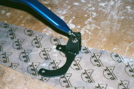
When the brace arrived I was
very pleased with the finish of the unit.
The shock tower mounts are powder coated black, and the anodized finish
was flawless. The chrome plating on the
fasteners also appeared to be well done.
However the brace came without any instructions for installation.
I decided to install the
driver’s side mount first since this appeared to be the easier of the two to
get to. First I removed the bolt
attaching the air intake tube and the bracket for the diagnostic socket using a
10mm socket. This allowed me to have a
direct view of the shock mount.
![]()
I then removed the two nuts
that attach the upper shock mount to the tower using a 14mm deep well
socket. It was then up to me to figure
out which of the two STB mounts go on which side and in what direction. After a couple of attempts I realized that
the only way the mounts would attach is the opposite of the way they appear in
the Moss catalog, with the open part of the bracket facing out instead of
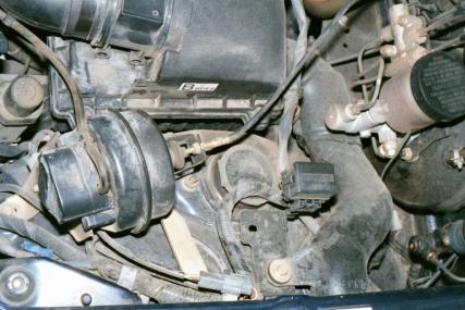
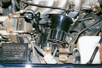
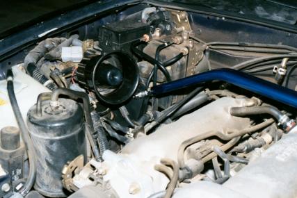
in. Shown below is the driver’s side
mount with the diagnostic socket reattached.
Note the placement of the wiring harness running through the upright
portion of the STB mount. Tighten the
shock mount nuts to 24 ft lbs.
![]()

Once the driver’s side was
complete, it was time to tackle the passenger’s side mount. This side is difficult because of the
placement of the siren for the factory alarm system of the 96 M-Edition, other
models will not have this problem. The
siren is attached to a saddle bracket that stretches between both of the nuts
that secure the upper shock mount to the body tower. There is also a grounding
wire from the siren under the nut towards the front of the car. Both of these nuts can be removed without
detaching the siren from the saddle bracket.
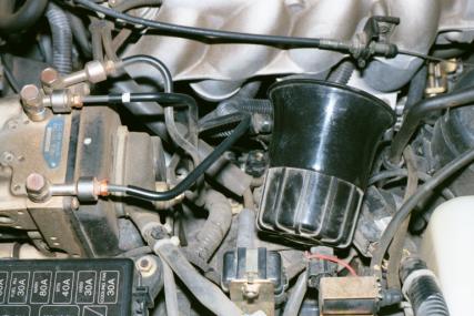
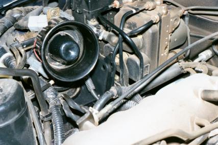
Once the siren is removed,
it is then possible to position the STB mount under the wiring harnesses and
get it into place. Again note that the
mount is positioned with the open part of the mount facing away from the
engine, and the attachment point for the brace to the firewall. You can see that one of the brake lines from
the ABS unit is in the way. This can be
fixed by gently bending the line towards the firewall by hand.
![]()
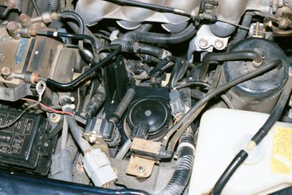
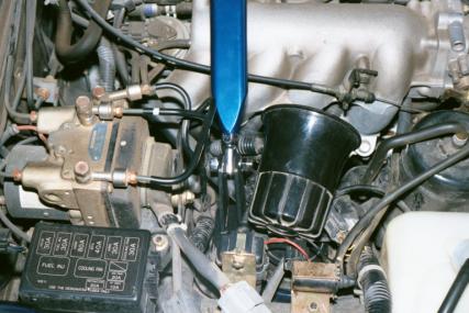
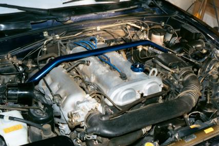
Once the brake line has been
bent clear, then re-install the siren with its saddle bracket to the top of the
STB mount, remembering to re-attach the grounding wire for the siren under the
nut towards the front of the car.
Torque the shock mount bolts to 24 ft lbs. This picture shows the siren re-attached and the brake line bent
away for clearance.
![]()
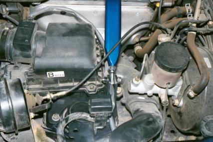
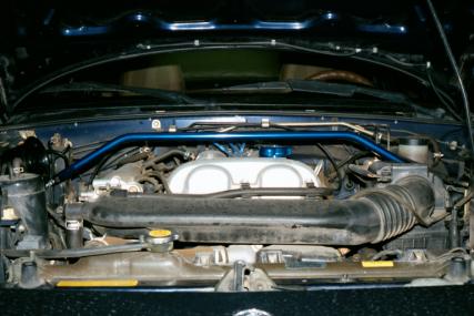
Here is another view of the
passenger’s side mount with the siren attached.
Now that the hard part is
over, the rest is easy. Adjust the
length of the fittings on the brace by screwing them in or out to get the holes
to line up with those in the mounts.
Remember that one side of the brace’s fittings is left-hand
threaded. Leave the nuts on the
fittings loose until later. Once you
get the fittings close, insert one end of the brace into one of the mounts and
secure it with the allen head bolt and nut provided. Do not yet tighten it down.
Then proceed to the other
side. Adjust the fitting to line up
with the bracket by again turning it to lengthen or shorten as needed. If you need to adjust the fitting on the
opposite end that is already attached, do this by turning the brace to get the
desired fit. Then attach this side of
the brace to the mount again using the allen head bolt and nut provided. Tighten the allen head bolt using a 8mm
allen wrench and a 14 mm box wrench. No
torque value for this so just make it tight (20 ft lbs?)
The final step is to tighten
the lock nuts on each of the fittings on the ends of the brace. Position the brace so that it lies flat and
tighten the lock nuts to the brace using a 17mm open end wrench. Again remember that one of the fittings is
left-hand threaded.
That’s all that there is to
it. It should take about 30 minutes to
install, and the same to remove. As you
can see it looks good too.
Another shot of the finished
product.
After installation I did
notice a reduction in cowl shake when hitting the neighborhood pot holes. Also, as other have reported, an STB
improves turn-in response when maneuvering at speed. I feel that it was worth the investment.