by Matt King
I first did this modification to my old NA several years ago. Since then I sold that car and acquired an NB. As the new car is black (and I'm shallow and vain) I hated the appearance of all the coloured bits on it. The orange corner reflectors soon got tinted, shortly followed by the side indicators.
I'm not a fan of reducing light output for obvious safety reasons, but I did also want to tint the centre brake light. So to compensate for the tint, I increased the light output over the capability of the standard 20W globe. Of course, you can do the mod without tinting the lens, and have a much more visible light as a result.
Changing to LEDs also does more than provide brighter light output. LEDs switch on noticeably faster than incandescent globes - up to 200 milliseconds sooner. This extra warning time can translate to several metres extra stopping distance for the car behind you, if you have to jam the brakes on.
Now, aftermarket LED brake lights are available, but I'm not a big fan. Sure they are great, but I prefer the blacked out look. Also I'm cheap, and a DIY job is much cheaper! All up, the parts cost only about $20.
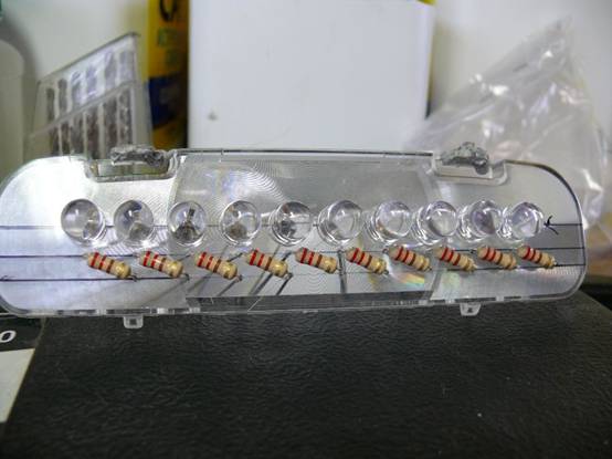
The end result uses ten high intensity 10mm LEDs, and (if not for the tint) looks entirely factory - until you hit the brake pedal!
Parts you'll need:
Tools:
Method: Remove the brake light assembly from the car. It is held in with two 10mm nuts. You may have to get off the white clips that hold the wiring harness first - these can be fiddly; I ended up cutting the cable-tie part and unscrewing. On the NB, a tab near the right nut also holds the assembly in place - pry this tab across with a screwdriver.
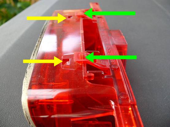
The housing swings open after undoing two clips (green arrows). Gently bend the two halves open. (You won't need to go past 90 degrees. If it cracks apart at the hinge, don't worry - it will still work fine.)
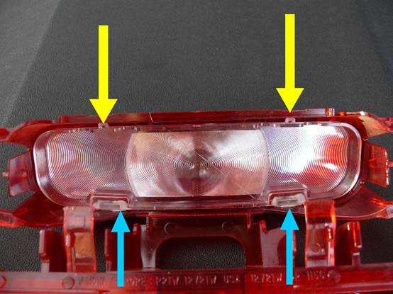
Next, remove the internal clear Fresnel lens. This piece will form the mounting plate for the LEDs. It is held in with two clips (yellow arrows), and some sticky adhesive on two tabs (blue arrows). Unclip the clips, insert a screwdriver into the hole vacated, and pry the tabs out of the slots.
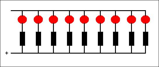
This is the circuit we are building (the red circles are the LEDs, and the black rectangles are the resistors). Each LED needs to be wired in the correct polarity - ie, the longer leg goes to the positive voltage side (the direction for the resistors doesn't matter). A resistor is used in line with each LED to regulate the current and prevent the smoke from getting out. (Electronic components are made of smoke. If the smoke gets out, they don't work any more... ;-) It doesn't matter if the resistor is before or after the LED.
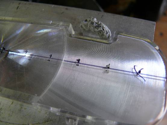
Mark up the lens for the LED and resistor hole locations. Ten LEDs will fit when spaced 13mm apart, and the pins of each are spaced 2.5mm apart. The resistors are mounted below, and angled so that they fit inside the housing. Once marked up, drill the holes with the 1mm drill bit.
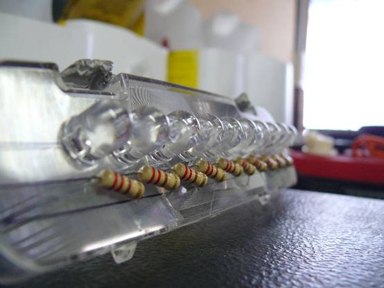
Place the LEDs and resistors into place, ensuring the LEDs are all oriented in the same way. The longer LED leg will be connected to the positive supply. Bend the legs so that the components stay in place.
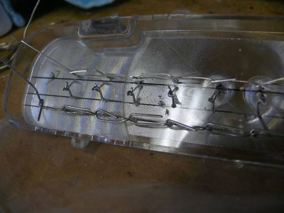
Twist the legs together as necessary to make the circuit. Solder the joints together, then trim the legs off neatly.
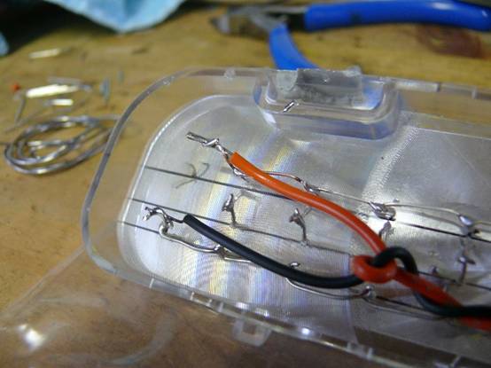
Solder on a pair of wires and use a cable tie to restrain them. At this point, you should be able to test the circuit by connecting the wires to the car battery. All going well, the LEDs should all light up. If they don't, try connecting the wires to the battery the other way. (This will also tell you which wire needs to connect to the positive side - take note of this)
The base of the old globe will form your plug. Very carefully (wearing gloves and eye protection!) smash the glass open, remove any broken glass, and tear out the filament. You should now have two exposed wire prongs left.
Plug the globe back into the car, and (with an assistant pushing the brake pedal) use the multimeter to determine which prong is the positive 12V one. (You can also visually track it through and check the continuity of the globe - the green wire in the car's harness is 12V and the black wire is ground)
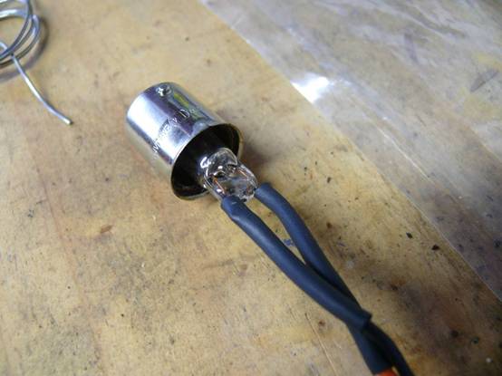
Next, slip some heatshrink over the wires, and solder them to the globe prongs (positive to positive, and negative to negative, as you determined earlier). Shrink the heatshrink in place to protect the joints (or use electrical tape).
You can now reassemble the lens assembly into the housing, and close up the housing. Assembly back into the car is straightforward - just reverse the removal procedure. Make sure you test the light before hitting the road again.
| Back to the Garage |
22 August, 2009 |
| [Home] - [FAQ] - [Search] - [Sponsors] - [Forums] |
| [Garage] - [Clubs] - [Contact Us] - [Disclosures] - [More...] |
Copyright
©1994-2024, Eunos Communications LLC
|