Jim Rossman
Well, I spent most of this afternoon on the turn signal problem. I got six or seven responses from the list, most said to check the bulbs, so I did that first. I replaced the bulbs on the front and rear passenger side. Same result. No flash on right side only. Even the four-way emergency flashers only worked on the driver side. Then I got a post from list member Lance Schall about a similar problem he had with solder failing on the circuit board of the flasher module. I followed his directions.
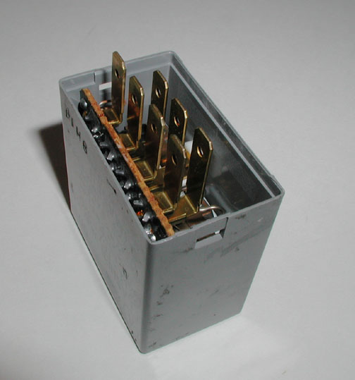
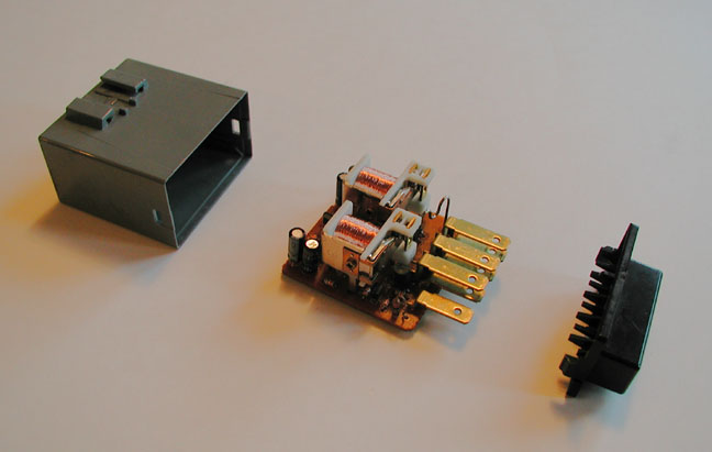
By following the clicking, I found the flasher module and when I squeezed it the right side would work for several seconds. After removing the module, I took off the plastic case and reconnected it to the plug to see which of the two solenoids controled the dead (right) side. FYI if you are looking at the board with the plug towards the bottom, the left solenoid controls the left side of the car and vice versa. I found a suspicious solder connection on the solenoid that controlled the right side. This connection was one of the larger ones on the board and looked worn or broken. I heated the connection and applied a bit more solder and reinstalled the module.
So far, so good. I drove the car all evening and the signals worked flawlessly. Since this is the second known occurance of this problem, perhaps the "garage" section of Miata.net would be interested in posting this for the rest of the group. I do however give all the credit to Lance Shall from Boulder Colorado.
Thanks to everyone who posted a response. You all are amazing.
Jim Rossman Tyler, Texas
I had the bad solder problem in my turn signal flasher unit and I wanted to add the following to the procedure for fixing it.
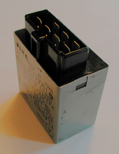
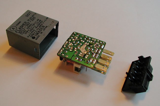
The flasher unit should be right in front of you when you look up from the clutch petal toward the hood of your car. On mine, it was labeled "flasher". Another way to identify it is to look for a grouping of three plugs and the flasher is the one with the widest plug. To remove the flasher unit, unplug the connector and pull the unit straight down. It is held in place by a clip only. There are no screws.
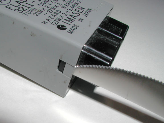
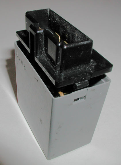
The flasher circuit board is inside the plastic housing. To open the unit, use a small flat screwdriver to free the plastic connector housing clips from the flasher unit housing. Once that's removed, the circuit board slides right out. on my circuit board it was easy to identify which solder was broken. It was the solder with a dark circle in the middle. At this point, I heated up my soldering iron, heated up the bad solder to "re-connect" the circuit board to the connector. The turn signal worked immediate after installation. You should try it out first and not putting the circuit board back into the plastic housing.
Prior to doing this, you should just check to see that you don't have a burnt out bulb.
Images from Lance Schall
From Murray Melvin
I went in and reflowed all the solder in my flasher and cleaned contacts like crazy but it still didn't work. As a last-ditch effort, I replaced every electrolytic capacitor on it. Most are common values but there's one that's 3.3uF. I didn't have one of those so I used 10uF. Once everything was back in the car, it worked beautifully. Never underestimate the value of replacing 25 year old electrolytic caps.